Subaru Crosstrek Service Manual: Dtc b1432 ambient temperature sensor circuit open (air-conditioner)
HVAC SYSTEM (AUTO A/C) (DIAGNOSTICS) > Diagnostic Procedure with Diagnostic Trouble Code (DTC)
DTC B1432 AMBIENT TEMPERATURE SENSOR CIRCUIT OPEN (AIR-CONDITIONER)
DTC detecting condition:
Ambient sensor circuit is open.
Trouble symptom:
Ambient temperature is falsely recognized, and the compartment temperature is adjusted.
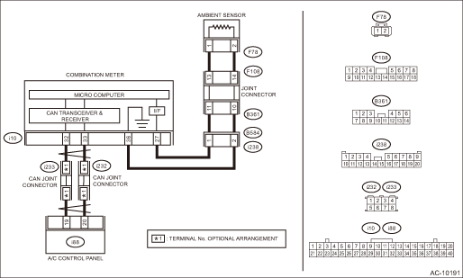
Wiring diagram:
Air conditioning system Air Conditioning System > WIRING DIAGRAM">
| STEP | CHECK | YES | NO |
1.CHECK CONNECTOR.
1) Check the connecting conditions of combination meter connector and ambient sensor connector.
2) Read the DTC using Subaru Select Monitor. Read Diagnostic Trouble Code (DTC)">
Is B1432 displayed?
Diagnostic Procedure with Diagnostic Trouble Code (DTC) > DTC B1432 AMBIENT TEMPERATURE SENSOR CIRCUIT OPEN (AIR-CONDITIONER)">Go to Step 2.
Even if DTC is displayed, the circuit has returned to a normal condition at this time. Reproduce the failure, and then perform the diagnosis again.
NOTE:
In this case, temporary poor contact of connector, temporary open or short circuit of harness may be the cause.
2.CHECK AMBIENT SENSOR.
1) Disconnect the ambient sensor.
2) Short the connector F78.
3) Read the DTC using Subaru Select Monitor. Read Diagnostic Trouble Code (DTC)">
Is B1433 displayed?
Replace the ambient sensor. Ambient Sensor > REMOVAL">
Diagnostic Procedure with Diagnostic Trouble Code (DTC) > DTC B1432 AMBIENT TEMPERATURE SENSOR CIRCUIT OPEN (AIR-CONDITIONER)">Go to Step 3.
3.CHECK HARNESS.
1) Restore the temporary shorted lines made in step 2.
2) Turn the ignition switch to ON.
3) Using the tester, measure the voltage between terminals.
Connector & terminal
(F78) No. 1 (+) — No. 2 (−):
Is the voltage 4.5 — 5.0 V?
Diagnostic Procedure with Diagnostic Trouble Code (DTC) > DTC B1432 AMBIENT TEMPERATURE SENSOR CIRCUIT OPEN (AIR-CONDITIONER)">Go to Step 4.
Repair or replace the open circuit of harness.
4.CHECK HARNESS (OPEN CIRCUIT).
1) Disconnect the connector from the combination meter.
2) Using a tester, check continuity between terminals.
Connector & terminal
(F78) No. 1 — (i10) No. 27:
(F78) No. 2 — (i10) No. 36:
Is there continuity?
Replace the combination meter. Combination Meter > REMOVAL">
Repair or replace the open circuit of harness.
 Dtc b1431 in-vehicle (post evaporator) temperature sensor circuit short-circuit
HVAC SYSTEM (AUTO A/C) (DIAGNOSTICS) > Diagnostic Procedure with Diagnostic Trouble Code (DTC)DTC B1431 IN-VEHICLE (POST EVAPORATOR) TEMPERATURE SENSOR CIRCUIT SHORT-CIRCUITDTC detecting condition: ...
 Dtc b1433 ambient temperature sensor circuit short-circuit (air-conditioner)
HVAC SYSTEM (AUTO A/C) (DIAGNOSTICS) > Diagnostic Procedure with Diagnostic Trouble Code (DTC)DTC B1433 AMBIENT TEMPERATURE SENSOR CIRCUIT SHORT-CIRCUIT (AIR-CONDITIONER)DTC detecting condition:Amb ...
Other materials:
Clock/calendar screen setting
1. Perform the preparation steps according
to "Preparation for screen settings"
2. Operate the "
" or "
"
switch to
select the "Clock" item. Then push the
button.
3. Push the
button once more.
4. Select "Analog Clock", "Digital Clock",
"Calendar" or "Off" by operating t ...
Caution
CRUISE CONTROL SYSTEM (DIAGNOSTICS) > General DescriptionCAUTIONAirbag system wiring harness is routed near the cruise control command switch.CAUTION:• Do not use the electrical test equipment on the airbag system wiring harnesses and connector circuits.• Be careful not to damage the ...
Removal
HVAC SYSTEM (HEATER, VENTILATOR AND A/C) > Heater and Cooling UnitREMOVALCAUTION:Before handling the airbag system components, refer to “CAUTION” of “General Description” in “AIRBAG SYSTEM”. General Description > CAUTION">1. Disconnect the ground ca ...
