Subaru Crosstrek Service Manual: Disassembly
DIFFERENTIALS > Rear Differential (T-type)
DISASSEMBLY
To detect the real cause of trouble, inspect the following items before disassembling.
• Tooth contact and backlash between hypoid driven gear and drive pinion
• Hypoid driven gear runout on its back surface
• Total preload of drive pinion
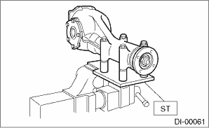
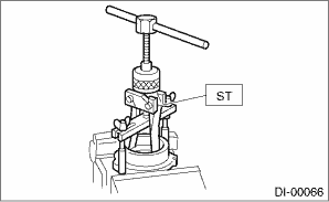
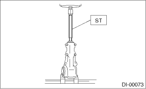
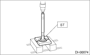
1. Set the ST on vise and install the differential assembly to ST.
| ST 398217700 | ATTACHMENT SET |
2. Remove the drain plug and filler plug.
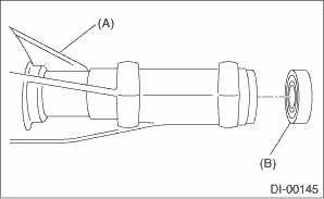
3. Remove the air breather cap.
NOTE:
• Do not attempt to remove the air breather cap unless necessary.
• Whenever the air breather cap is removed, replace it with a new part.
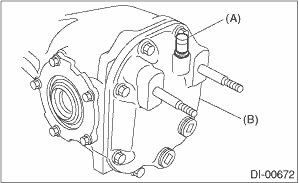
(A) | Air breather cap |
(B) | Rear cover |
4. Remove the bolts, and then remove the rear cover.
5. Remove the stud bolts from rear cover if necessary.
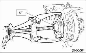
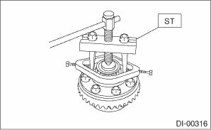
6. Remove the side retainer attachment bolts, set the ST to differential case, and extract the side retainers RH and LH with a puller.
NOTE:
• Side retainer shim of each side should be kept together with its mating retainer.
• Keep the side retainers separate by attaching tags or in similar ways to make it possible to identify RH and LH sides during reassembly.
| ST 398457700 | ATTACHMENT |
7. Remove the oil seal and O-ring from the side retainer.
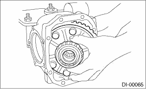
8. Pull out the differential case assembly from the differential carrier.
NOTE:
Be careful not to hit the teeth of hypoid driven gear against the differential carrier.
9. When replacing the side bearing, remove the side bearing race from the side retainer using ST.
| ST 398527700 | PULLER ASSY |
10. Using the ST, remove the side bearing cone.
NOTE:
• Do not attempt to disassemble the parts unless necessary.
• Set the ST so that its claws catch the edge of the side bearing cone.
• Never mix up the RH and LH side bearing races and cones.
| ST 18759AA000 | PULLER ASSY |
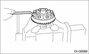
11. Remove the hypoid driven gear by loosening hypoid driven gear bolts.
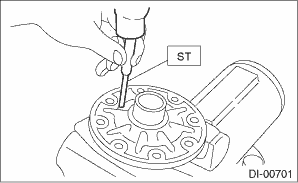
12. Remove the pinion shaft lock pin from hypoid driven gear side using ST.
| ST 899904100 | STRAIGHT PIN REMOVER |
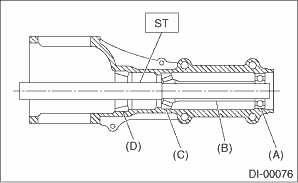
13. Draw out the pinion mate shaft, and remove pinion mate gears, pinion mate gear washers, side gears, and side gear thrust washers.
NOTE:
The gears and washers should be marked with RH or LH, front or rear, or kept separately.
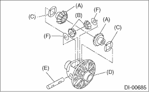
(A) | Side gear |
(B) | Pinion mate gear |
(C) | Side gear thrust washer |
(D) | Differential case |
(E) | Pinion mate shaft |
(F) | Pinion mate gear washer |
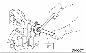
14. Remove the self-locking nut while securing the companion flange with ST.
| ST 498427200 | FLANGE WRENCH |
15. Extract the companion flange with a puller.
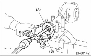
(A) | Companion flange |
(B) | Puller |
16. Press the end of drive pinion shaft using ST and remove the rear bearing cone, pinion height adjusting washer, preload adjusting spacer and washer.
NOTE:
Hold the drive pinion so as not to drop it.
| ST 398467700 | DRIFT |
17. Remove the rear bearing cone from drive pinion by supporting the bearing cone with ST.
NOTE:
Place the replacer so that its center-recessed side faces the bearing cone.
| ST 398517700 | REPLACER |
18. Remove the front oil seal from differential carrier using ST.
| ST 398527700 | PULLER ASSY |
(A) | Differential carrier |
(B) | Front oil seal |
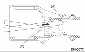
19. Remove the pilot bearing together with the front bearing cone and spacer using the ST.
| ST 398467700 | DRIFT |
(A) | Pilot bearing |
(B) | Spacer |
(C) | Front bearing |
(D) | Rear bearing race |
20. When replacing the bearings, use a brass bar to tap out the front bearing race and rear bearing race in this order to remove them.
(A) | 2 cutout portions along diagonal lines |
(B) | Tap alternately with brass bar. |
 Assembly
DIFFERENTIALS > Rear Differential (T-type)ASSEMBLYNOTE:• Assemble in the reverse order of disassembly.• Check and adjust each part during assembly.• Keep the shims and washers in ...
 Inspection
DIFFERENTIALS > Rear Differential (T-type)INSPECTIONWash all the disassembled parts clean, and examine them for wear, damage and other defects. Repair or replace the defective parts as necessary.1. ...
Other materials:
Removal
REAR SUSPENSION > Rear Sub FrameREMOVAL1. Disconnect the ground cable from battery. NOTE">2. Lift up the vehicle, and then remove the rear wheels.3. Remove the bolts and clips, and remove the under cover - front.(1)Under cover - front(2)Mud guard - front(3)Spacer - under cover4. Remove t ...
Removal
LIGHTING SYSTEM > Front Fog Light AssemblyREMOVAL1. Disconnect the ground cable from battery. NOTE">2. Lift up the vehicle.3. Remove the screw and clips, and turn over the front side of the mud guard - front.4. From the bottom of the bumper face - front, remove the fog light assembly - f ...
Removal
FUEL INJECTION (FUEL SYSTEMS)(H4DO) > Fuel Level SensorREMOVALWARNING:Place “NO OPEN FLAMES” signs near the working area.CAUTION:• Be careful not to spill fuel.• If the fuel gauge indicates that two thirds or more of the fuel is remaining, be sure to drain fuel before star ...
