Subaru Crosstrek Service Manual: Assembly
DIFFERENTIALS > Rear Differential (T-type)
ASSEMBLY
NOTE:
• Assemble in the reverse order of disassembly.
• Check and adjust each part during assembly.
• Keep the shims and washers in order, so that they are not improperly installed.
• Thoroughly clean the surfaces on which the shims, washers and bearings are to be installed.
• Apply differential gear oil when installing the bearings and thrust washers.
• Be careful not to mix up the RH and LH bearing races.
• Replace the gasket, oil seal and O-ring with a new part.
• Be careful not to mix up the rear differential side oil seal RH and LH.
• Apply differential gear oil to the lips when installing the oil seal.
1. Adjusting preload for front and rear bearings
NOTE:
Adjust the bearing preload between front and rear bearings with preload adjusting spacer and washer. Pinion height adjusting washer is not affected by this adjustment. The adjustment must not be carried out with oil seal inserted.
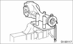
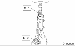
(1) Install the rear bearing race into the differential carrier using ST1 and ST2.
| ST1 398477701 | HANDLE |
| ST2 398477703 | DRIFT 2 |
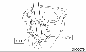
(2) Install the front bearing race to the differential carrier using ST1 and ST2.
NOTE:
Use a new front bearing race.
| ST1 398477701 | HANDLE |
| ST2 398477702 | DRIFT |
(3) Insert ST1 into the differential carrier with the pinion height adjusting washer and rear bearing cone fitted onto it.
NOTE:
• At this time, install a provisionally selected or previously used pinion height adjusting washer. Measure and record the thickness.
• If tooth contact (drive pinion, hypoid driven gear) is normal in the inspection before disassembling, verify that the washer is not deformed, and then re-use the used washer.
(4) Install the preload adjusting spacer and washer, front bearing cone, ST2, companion flange and self-locking nut.
NOTE:
Use new front bearing cone.
| ST1 398507702 | DUMMY SHAFT |
| ST2 398507703 | DUMMY COLLAR |
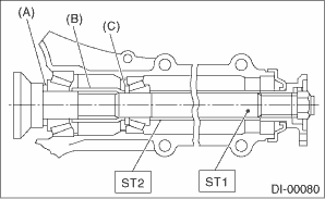
(A) | Pinion height adjusting washer |
(B) | Preload adjusting spacer |
(C) | Preload adjusting washer |
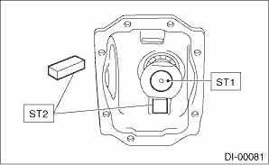
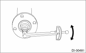
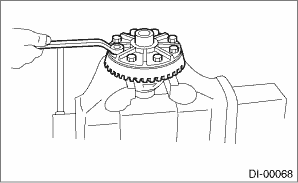
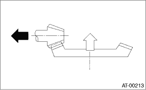
(5) Turn the ST1 by hand to smooth the bearing, and tighten the self-locking nut while measuring the initial load or initial torque with a spring scale or torque wrench. Select the preload adjusting washer and spacer so that the specified preload is obtained when nut is tightened to the specified torque.
NOTE:
• Use a new self-locking nut.
• Measure the preload in direction of tangent to the flange.
• Be careful not to give excessive preload.
• When tightening the self-locking nut, lock ST1 with ST2 as shown in the figure.
| ST1 398507702 | DUMMY SHAFT |
| ST2 398507704 | BLOCK |
Tightening torque:
181.5 N·m (18.5 kgf-m, 133.9 ft-lb)
Initial load:
18.1 — 38.8 N (1.8 — 4.0 kgf, 4.1 — 8.7 lbf)
Initial torque:
0.69 — 1.47 N·m (0.07 — 0.15 kgf-m, 0.51 — 1.08 ft-lb)
Preload adjusting washer | |
Part No. | Thickness mm (in) |
383705200 | 2.59 (0.1020) |
383715200 | 2.57 (0.1012) |
383725200 | 2.55 (0.1004) |
383735200 | 2.53 (0.0996) |
383745200 | 2.51 (0.0988) |
383755200 | 2.49 (0.0980) |
383765200 | 2.47 (0.0972) |
383775200 | 2.45 (0.0965) |
383785200 | 2.43 (0.0957) |
383795200 | 2.41 (0.0949) |
383805200 | 2.39 (0.0941) |
383815200 | 2.37 (0.0933) |
383825200 | 2.35 (0.0925) |
383835200 | 2.33 (0.0917) |
383845200 | 2.31 (0.0909) |
Preload adjusting spacer | |
Part No. | Length mm (in) |
383695201 | 56.2 (2.213) |
383695202 | 56.4 (2.220) |
383695203 | 56.6 (2.228) |
383695204 | 56.8 (2.236) |
383695205 | 57.0 (2.244) |
383695206 | 57.2 (2.252) |
2. Adjusting drive pinion height:
Adjust the drive pinion height with pinion height adjusting washer installed between the rear bearing cone and the back of pinion gear.
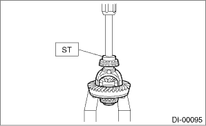
(1) Attach the ST2.
| ST1 398507702 | DUMMY SHAFT |
| ST2 398507701 | DIFFERENTIAL CARRIER GAUGE |
| ST3 398507703 | DUMMY COLLAR |
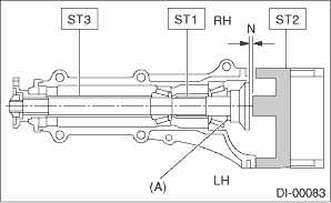
(A) | Pinion height adjusting washer |
(2) Measure the clearance “N” between the end of ST2 and the end surface of ST1 by using a thickness gauge.
NOTE:
Make sure there is no clearance between the differential carrier and ST2.
| ST1 398507702 | DUMMY SHAFT |
| ST2 398507701 | DIFFERENTIAL CARRIER GAUGE |
(3) Obtain the thickness of pinion height adjusting washer to be inserted from the following formula, and replace the temporarily installed washer with this one.
T = To + N − (H ? 0.01) − 0.20 mm (0.0079 in)
T | Thickness of pinion height adjusting washer mm (in) |
|
To | Thickness of washer temporarily inserted mm (in) |
|
N | Clearance of thickness gauge mm (in) |
|
H | Figure marked on drive pinion head |
|
Memo:
| ||
(Example of calculation)
To = 3.39 mm (0.1335 in)
N = 0.24 mm (0.0094 in)
H = + 1
T = 3.39 mm (0.1335 in) + 0.24 mm (0.0094 in) − 0.01 mm (0.0004 in) − 0.20 mm (0.0079 in) = 3.42 mm (0.1346 in)
Result: Thickness = 3.42 mm (0.1346 in)
Therefore use washer 383605200.
Pinion height adjusting washer | |
Part No. | Thickness mm (in) |
383495200 | 3.09 (0.1217) |
383505200 | 3.12 (0.1228) |
383515200 | 3.15 (0.1240) |
383525200 | 3.18 (0.1252) |
383535200 | 3.21 (0.1264) |
383545200 | 3.24 (0.1276) |
383555200 | 3.27 (0.1287) |
383565200 | 3.30 (0.1299) |
383575200 | 3.33 (0.1311) |
383585200 | 3.36 (0.1323) |
383595200 | 3.39 (0.1335) |
383605200 | 3.42 (0.1346) |
383615200 | 3.45 (0.1358) |
383625200 | 3.48 (0.1370) |
383635200 | 3.51 (0.1382) |
383645200 | 3.54 (0.1394) |
383655200 | 3.57 (0.1406) |
383665200 | 3.60 (0.1417) |
383675200 | 3.63 (0.1429) |
383685200 | 3.66 (0.1441) |
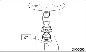
3. Install the selected pinion height adjusting washer on drive pinion, and press the rear bearing cone into position with ST.
| ST 398177700 | INSTALLER |
4. Insert the drive pinion into the differential carrier, and install the preselected preload adjusting spacer and washer.
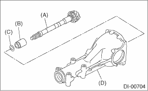
(A) | Drive pinion |
(B) | Preload adjusting spacer |
(C) | Preload adjusting washer |
(D) | Differential carrier |
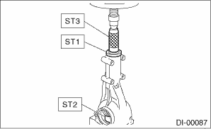
5. Press-fit the front bearing cone with ST1, ST2 and ST3.
NOTE:
Use new front bearing cone.
| ST1 398507703 | DUMMY COLLAR |
| ST2 399780104 | WEIGHT |
| ST3 899580100 | INSTALLER |
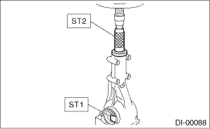
6. Insert the spacer, then press-fit the pilot bearing with ST1 and ST2.
NOTE:
Use a new pilot bearing.
| ST1 399780104 | WEIGHT |
| ST2 899580100 | INSTALLER |
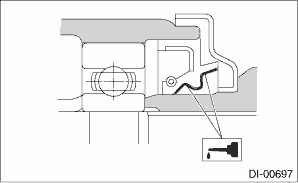
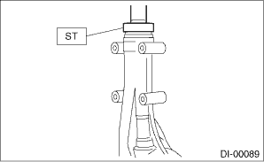
7. Using the ST, install the oil seal.
NOTE:
• Use a new oil seal.
• Press-fit until the oil seal end comes 1 mm (0.04 in) inward from end of carrier.
• Apply differential gear oil to the oil seal lips.
| ST 498447120 | INSTALLER |
8. Press-fit the companion flange with ST1 and ST2.
NOTE:
Be careful not to damage the bearing.
| ST1 899874100 | INSTALLER |
| ST2 399780104 | WEIGHT |
9. Apply seal material on the drive pinion shaft thread and new self-locking nut seat.
Seal material:
THREE BOND 1324 (Part No. 004403042) or equivalent
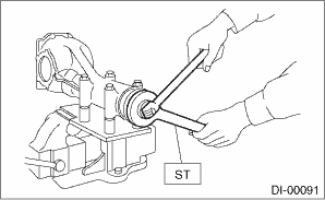
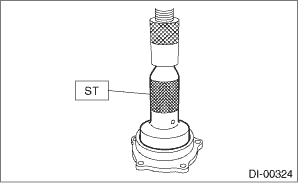
10. Attach the new self-locking nut and use the ST to fix the companion flange in place, then tighten the self-locking nut.
Tightening torque:
181.5 N·m (18.5 kgf-m, 133.9 ft-lb)
| ST 498427200 | FLANGE WRENCH |
11. Check the initial torque or initial load.
Initial load:
18.1 — 38.8 N (1.8 — 4.0 kgf, 4.1 — 8.7 lbf)
Initial torque:
0.69 — 1.47 N·m (0.07 — 0.15 kgf-m, 0.51 — 1.08 ft-lb)
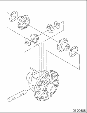
12. Assembling differential case
(1) Install the side gears and pinion mate gears, with their side gear thrust washers, pinion mate gear washer, and pinion mate shaft, into the differential case.
NOTE:
• Apply gear oil on both sides of the washer and on the pinion mate shaft before installing.
• Insert the pinion mate shaft into the differential case by aligning the pin holes.
(2) Measure the side gear backlash.
Side gear backlash:
0.10 — 0.20 mm (0.004 — 0.008 in)

(3) Adjust the backlash as specified by selecting side gear thrust washer.
Side gear thrust washer | |
Part No. | Thickness mm (in) |
383445201 | 0.75 — 0.80 (0.0295 — 0.0315) |
383445202 | 0.80 — 0.85 (0.0315 — 0.0335) |
383445203 | 0.85 — 0.90 (0.0335 — 0.0354) |
(4) Check the condition of rotation after applying oil to the gear tooth surfaces and washer surfaces.
(5) Drive the pinion shaft lock pin into the differential case.
NOTE:
Use a new pinion shaft lock pin.
| ST 899904100 | STRAIGHT PIN REMOVER |
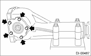
13. Install the driven gear to the differential case.
NOTE:
• Before installing bolts, apply seal material to bolt threads.
Seal material:
THREE BOND 1324 (Part No. 004403042) or equivalent
• Make sure there is no clearance between the differential case and driven gear.
• Tighten opposing bolts in order.
Tightening torque:
103 N·m (10.5 kgf-m, 76.0 ft-lb)
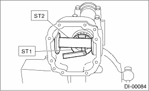
14. Using the ST, press-fit the side bearing to the differential case.
| ST 398487700 | DRIFT |
15. Using the ST, press-fit the side bearing outer race to the side retainer.
CAUTION:
Make sure that the bearing outer races and cones are properly assembled.
| ST 398417700 | DRIFT |
16. Side retainer shim adjustment
(1) The hypoid driven gear backlash and side bearing preload can be adjusted by the side retainer shim thickness.
(2) Install the differential case assembly into differential carrier in the reverse order of disassembly.
NOTE:
Be careful not to hit the teeth of hypoid driven gear against the differential carrier.
(3) Install the side retainer shim.
NOTE:
• Be careful not to mix up the side retainer shim RH and LH.
• Replace broken or corroded side retainer shims with a new part of the same thickness.
Side retainer shim | |
Part No. | Thickness mm (in) |
383475201 | 0.20 (0.0079) |
383475202 | 0.25 (0.0098) |
383475203 | 0.30 (0.0118) |
383475204 | 0.40 (0.0157) |
383475205 | 0.50 (0.0197) |
(4) Align the arrow mark on the differential carrier with the arrow mark on the side retainer when installing the side retainer.
NOTE:
Be careful that side bearing race is not damaged by the bearing roller.
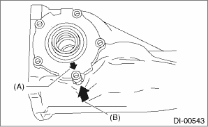
(A) | Arrow mark (on the side retainer) |
(B) | Arrow mark (on the differential carrier) |
(5) Tighten the side retainer bolts.
Tightening torque:
10.5 N·m (1.1 kgf-m, 7.7 ft-lb)
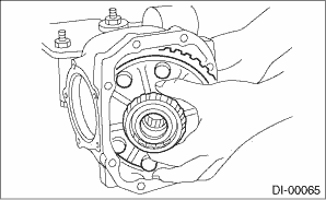
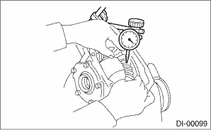
(6) Measure the hypoid driven gear to drive pinion backlash. Set the magnet base on differential carrier. Align the contact point of dial gauge with tooth face of hypoid driven gear, and move hypoid driven gear while holding drive pinion still. Read the value indicated on dial gauge. If the backlash is outside the standard range, adjust the side retainer shim by the following method.
•When backlash is less than 0.1 mm (0.004 in):
Reduce the thickness of shim on the back side of the hypoid driven gear and increase the thickness of shims on the teeth side of the hypoid driven gear.
•When backlash exceeds 0.2 mm (0.008 in):
Increase the thickness of shim on the back side of the hypoid driven gear and reduce the thickness of shims on the teeth side of the hypoid driven gear.
Backlash:
0.10 — 0.20 mm (0.004 — 0.008 in)
(7) Measure the total preload of the drive pinion. If the total preload is outside the specification range, adjust the thickness of side retainer shims, increasing/reducing both shims by an even amount at a time.
Total preload:
20.7 — 54.4 N (2.1 — 5.5 kgf, 4.7 — 12.2 lbf)
17. Recheck the hypoid driven gear to drive pinion backlash.
Backlash:
0.10 — 0.20 mm (0.004 — 0.008 in)
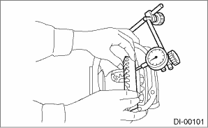
18. Check pinion and hypoid driven gears rotate smoothly and make sure of the hypoid driven gear runout on its back surface. If the hypoid driven gear runout on its back surface exceeds the specification, check for any foreign objects between the hypoid driven gear and differential case, and for any deformation of the differential case or hypoid driven gear.
Hypoid driven gear back surface runout:
0.05 mm (0.002 in)
19. Check and adjustment of the tooth contact of hypoid driven gear and drive pinion
(1) Apply lead-free red dye evenly on the both sides of three to four teeth of the hypoid driven gear. Check the contact pattern after rotating the hypoid driven gear several revolutions back and forth until a definite contact pattern appears on the hypoid driven gear.
(2) When the contact pattern is not correct, readjust.
NOTE:
Be sure to wipe off the lead-free red dye completely after the adjustment is completed.
• Correct tooth contact
Check item: Tooth contact pattern is slightly shifted toward toe side under no-load rotation. (When driving, it moves towards the heel side.)
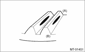
(A) | Toe side |
(B) | Heel side |
• Face contact
Check item: Backlash is too large.
Contact pattern
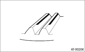
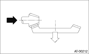
Corrective action: Increase thickness of pinion height adjusting washer according to the procedure for bringing drive pinion close to hypoid driven gear side.
• Flank contact
Check item: Backlash is too small.
Contact pattern
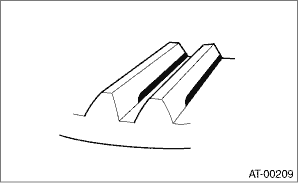
Corrective action: Reduce the thickness of pinion height adjusting washer according to the procedure for bringing drive pinion away from hypoid driven gear.
 Adjustment
DIFFERENTIALS > Rear Differential (T-type)ADJUSTMENT1. SIDE GEAR BACKLASHAdjust the side gear backlash. Rear Differential (T-type) > ASSEMBLY">2. HYPOID DRIVEN GEAR BACKLASHAdjust hypoi ...
 Disassembly
DIFFERENTIALS > Rear Differential (T-type)DISASSEMBLYTo detect the real cause of trouble, inspect the following items before disassembling.• Tooth contact and backlash between hypoid driven g ...
Other materials:
Removal
AIRBAG SYSTEM > Satellite Safing SensorREMOVALCAUTION:Before handling the airbag system components, refer to “CAUTION” of “General Description” in “AIRBAG SYSTEM”. General Description > CAUTION">1. Turn the ignition switch to OFF.2. Disconnect the g ...
Note
LIGHTING SYSTEM > Interior Light SystemNOTEFor operation procedures of each component of the interior light system, refer to the respective section.• Spot map light: Spot Map Light">• Room light: Room Light">• Luggage room light: Luggage Room Light">&b ...
Assembly
SEATS > Rear SeatASSEMBLYCAUTION:• Do not reuse hog rings.• Secure the hog ring using hog ring pliers.• Install the hog rings to the specified points securely and make sure that there is no wrinkle or twisting on the cover COMPL - rear backrest.1. Assemble the cover COMPL - rear ...
