Subaru Crosstrek Service Manual: Control module i/o signal Electrical specification
INSTRUMENTATION/DRIVER INFO (DIAGNOSTICS) > Control Module I/O Signal
ELECTRICAL SPECIFICATION
• Combination meter
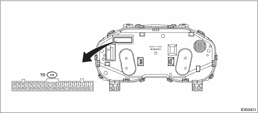
Terminal No. | Content | Terminal No. | Content |
1 | Security indicator | 27 | Ambient sensor |
2 | Charge warning light | 28 | UART (MFD) |
3 | Oil pressure warning light | 29 | Steering switch (+) |
4 | RH turn indicator | 30 | Pedestrian alert device |
6 | LH turn indicator | 32 | CAN communication line (−) |
8 | Auto headlight beam leveler warning light | 33 | CAN communication line (+) |
15 | Driver’s seat belt switch | 36 | Ambient sensor GND |
16 | Passenger’s seat belt switch | 37 | Fuel level sensor GND |
20 | Ignition power supply | 38 | GND |
21 | Washer fluid level sensor | 39 | Backup ignition power supply |
23 | Brake fluid level switch | 40 | Battery power supply |
25 | Fuel level sensor | — | — |
Terminal No. | Item | Measuring condition | Standard |
1 ←> Chassis ground | Voltage | Security indicator light off > on | 0 V > 10 — 14 V |
2 ←> Chassis ground | Voltage | Charge warning light off > on | 0 V > 10 — 14 V |
3 ←> Chassis ground | Voltage | Oil pressure warning light off > on | 0 V > 10 — 14 V |
4 ←> Chassis ground | Voltage | RH turn indicator off > on | 0 V > 10 — 14 V |
6 ←> Chassis ground | Voltage | LH turn indicator off > on | 0 V > 10 — 14 V |
8 ←> Chassis ground | Voltage | Auto headlight beam leveler warning light off > on | 0 V > 10 — 14 V |
15 ←> Chassis ground | Resistance | Driver’s seat belt switch ON | Less than 1 ? |
16 ←> Chassis ground | Resistance | Passenger’s seat belt switch ON | Less than 1 ? |
20 ←> Chassis ground | Voltage | IG OFF > ON | 0 V > 10 — 14 V |
21 ←> Chassis ground | — | Washer fluid level sensor | — |
23 ←> Chassis ground | — | Brake fluid level switch | — |
25 ←> 37 | Resistance | Fuel level sensor | 10 — 600 ? |
27 ←> 36 | Resistance | Ambient sensor | 1 — 35 k? |
28 (UART) ←> Chassis ground | — | Cannot be measured | — |
32 (CAN−) ←> Chassis ground | — | Cannot be measured | — |
33 (CAN+) ←> Chassis ground | — | Cannot be measured | — |
34 ←> Chassis ground | Resistance | Always | Less than 1 ? |
35 ←> Chassis ground | Resistance | Always | Less than 1 ? |
36 ←> Chassis ground | Resistance | Always | Less than 1 ? |
37 ←> Chassis ground | Resistance | Always | Less than 1 ? |
38 ←> Chassis ground | Resistance | Always | Less than 1 ? |
39 ←> Chassis ground | Resistance | Always | Less than 1 ? |
40 ←> Chassis ground | Voltage | Always | 10 — 14 V |
• MFD
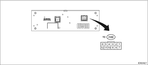
Terminal No. | Content | Terminal No. | Content |
1 | Battery power supply | 7 | — |
2 | GND | 8 | — |
3 | Ignition power supply | 9 | UART (meter) |
4 | Switch communication line (−) | 10 | Passenger’s airbag ON |
5 | CAN communication line (−) | 11 | Passenger’s airbag OFF |
6 | CAN communication line (+) | 12 | Switch communication line (+) |
Terminal No. | Item | Measuring condition | Standard |
1 (+B) ←> Chassis ground | Voltage | Always | 10 — 14 V |
2 (GND) ←> Chassis ground | Resistance | Always | Less than 1 ? |
3 (IGN) ←> Chassis ground | Voltage | IG OFF > ON | 0 V > 10 — 14 V |
4 (STR−) ←> Chassis ground | — | Cannot be measured (switch communication line) | — |
5 (CAN−) ←> Chassis ground | — | Cannot be measured (CAN communication line) | — |
6 (CAN+) ←> Chassis ground | — | Cannot be measured (CAN communication line) | — |
9 (UART) ←> Chassis ground | — | Cannot be measured (meter communication line) | — |
10 ←> Chassis ground | Voltage | Passenger’s airbag ON indicator (when illuminating) | Less than 1 V |
11 ←> Chassis ground | Voltage | Passenger’s airbag OFF indicator (when illuminating) | Less than 1 V |
12 (STR+) ←> Chassis ground | — | Cannot be measured (switch communication line) | — |
 Clear memory mode Operation
INSTRUMENTATION/DRIVER INFO (DIAGNOSTICS) > Clear Memory ModeOPERATION1. COMBINATION METER1. On «Start» display, select «Diagnosis».2. On «Vehicle selection» display, input the target vehicle ...
 Electrical component location Location
INSTRUMENTATION/DRIVER INFO (DIAGNOSTICS) > Electrical Component LocationLOCATION(1)Combination meter(2)MFD(3)Data link connector ...
Other materials:
Disassembly
SECURITY AND LOCKS > Ignition Key LockDISASSEMBLY1. Remove the immobilizer antenna assembly or the ignition switch illumination. Immobilizer Antenna > REMOVAL">2. Release the claws, and pull the key warning switch downwards to remove.3. Remove the screws and remove the key lock soleno ...
To arm the system using access
key/remote transmitter
1. Close all windows and the moonroof (if
equipped).
2. Remove the key from the ignition
switch (models without "keyless access
with push-button start system")/turn the
push-button ignition switch to the "OFF"
position (models with "keyless access with
push-button start system").
3. Open ...
Installation
INTAKE (INDUCTION)(H4DO) > Air Cleaner CaseINSTALLATION1. Install the bolt (A) and nut (B) which secure the air cleaner case (front) to the body.Tightening torque:Bolt (A)6 N·m (0.6 kgf-m, 4.4 ft-lb)Nut (B)7.5 N·m (0.8 kgf-m, 5.5 ft-lb)2. Install the air cleaner case (rear) and air ...
