Subaru Crosstrek Service Manual: Component
SECURITY AND LOCKS > General Description
COMPONENT
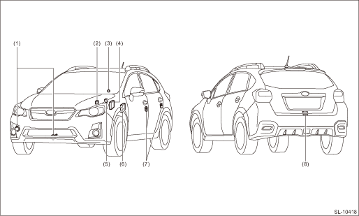
1. DOOR LOCK ASSEMBLY

(A) | Front | (B) | Rear | ||
(1) | Grommet - screw | (9) | Key lock - door (driver’s seat only) | (17) | Frame ASSY - rear door outer |
(2) | Remote ASSY - door | (10) | Spacer - door handle outer B | ||
(3) | Cap remote | (11) | Spacer - door handle outer A | Tightening torque: N·m (kgf-m, ft-lb) | |
(4) | Latch & actuator ASSY - front | (12) | Frame ASSY - front door outer | T1: | 6.5 (0.66, 4.8) |
(5) | Handle - door outer (model with keyless access with push button start) | (13) | Striker - door | T2: | 7.5 (0.76, 5.5) |
(6) | Cover - handle front outer (passenger’s seat) | (14) | Screw | T3: | 18 (1.84, 13.3) |
(7) | Handle - door outer (model without keyless access with push button start) | (15) | Latch & actuator ASSY - rear | ||
(8) | Cover - handle front outer (driver’s seat) | (16) | Cover - handle rear outer | ||
2. REAR GATE LOCK

(1) | Latch & actuator - rear gate | Tightening torque: N·m (kgf-m, ft-lb) | |||
(2) | Striker - rear gate | T: | 25 (2.55, 18.4) | ||
3. FRONT HOOD LOCK

(1) | Lock ASSY - front hood | (3) | Bracket - opener handle | Tightening torque: N·m (kgf-m, ft-lb) | |
(2) | Cable - front hood | (4) | Striker - front hood | T1: | 7.5 (0.76, 5.5) |
T2: | 33 (3.36, 24.3) | ||||
4. REMOTE OPENER

(1) | Cover - handle | (3) | Cable ASSY - fuel | Tightening torque: N·m (kgf-m, ft-lb) | |
(2) | Pull handle - opener | (4) | Holder | T: | 7.5 (0.76, 5.5) |
5. KEYLESS ENTRY SYSTEM

(1) | Body integrated unit | (3) | Keyless entry control module | (5) | Door switch |
(2) | Power window main switch | (4) | Rear gate latch switch |
6. SECURITY SYSTEM
(1) | Horn assembly | (4) | Body integrated unit | (7) | Door switch |
(2) | Horn relay (in main fuse box) | (5) | Turn signal and hazard module | (8) | Rear gate latch switch |
(3) | Security indicator light (in combination meter) | (6) | Impact sensor (driver’s seat instrument panel side) (dealer option) |
7. KEYLESS ACCESS WITH PUSH BUTTON START SYSTEM
NOTE:
Refer to “Electrical Component Location” of “KEYLESS ACCESS WITH PUSH BUTTON START SYSTEM (DIAGNOSTICS)” section. Electrical Component Location">
 Preparation tool
SECURITY AND LOCKS > General DescriptionPREPARATION TOOL1. SPECIAL TOOLILLUSTRATIONTOOL NUMBERDESCRIPTIONREMARKS — SUBARU SELECT MONITOR 4Used for setting of each function and troubleshooting for ...

Other materials:
Assembly
MANUAL TRANSMISSION AND DIFFERENTIAL(5MT) > Center DifferentialASSEMBLYInstall the ball bearings.CAUTION:Do not apply a load in excess of 10 kN (1 ton, 1.1 US ton, 1.0 Imp ton).NOTE:Use a new ball bearing.(A)Ball bearing ...
Radiator cap Inspection
COOLING(H4DO) > Radiator CapINSPECTION1. Check that the radiator cap does not have deformation, cracks or damage.2. Attach the radiator cap tester to radiator cap.3. Increase pressure until the radiator cap tester gauge needle stops. Radiator cap is functioning properly if it holds the service li ...
Inspection
FUEL INJECTION (FUEL SYSTEMS)(H4DO) > Oil Control SolenoidINSPECTION1. Check that the oil control solenoid has no deformation, cracks or other damages.2. Measure the resistance between the oil control solenoid terminals.Terminal No.Standard1 and 27.25±0.4 ? (when 20°C (68°F ...
