Subaru Crosstrek Service Manual: Component
BRAKE > General Description
COMPONENT
1. FRONT DISC BRAKE
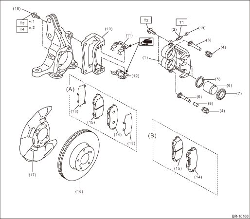
(A) | Shim-separate brake pad type | (B) | Shim-integrated brake pad type | ||
(1) | Caliper body | (11) | Pad clip - upper | (19) | Cap - bleeder |
(2) | Bleeder - screw | (12) | Pad clip - lower | ||
(3) | Guide pin - front brake (black) | (13) | Shim - disc brake front | *1: | 17 mm (width across flats) |
(4) | Pin boot | (14) | Pad - disc brake front outer | *2: | 19 mm (width across flats) |
(5) | Piston seal | (15) | Pad - disc brake front inner | ||
(6) | Piston - disc brake | (16) | Disc rotor | Tightening torque: N·m (kgf-m, ft-lb) | |
(7) | Piston boot | (15) | Pad - disc brake front inner | T1: | 8 (0.82, 5.9) |
(8) | Lock pin - sleeve | (16) | Disc rotor | T2: | 27 (2.75, 19.9) |
(9) | Lock pin - front brake (silver) | (17) | Back plate - front brake | T3: | 80 (8.16, 59) |
(10) | Support - front disc brake | (18) | Mounting bolt | T4: | 135 (13.8, 99.6) |
2. REAR DISC BRAKE
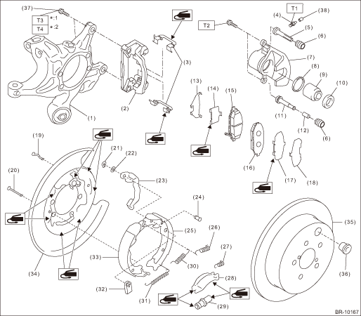
(1) | Housing ASSY - rear axle | (17) | Shim - disc brake rear inner | (33) | Parking brake shoe (primary) |
(2) | Support - rear disc brake | (18) | Shim - disc brake rear outer | (34) | Back plate - rear brake |
(3) | Pad clip - rear brake | (19) | Pin - secondary shoe hold-down | (35) | Disc rotor (solid type) |
(4) | Bleeder - screw | (20) | Pin - primary shoe hold-down | (36) | Adjusting hole cover |
(5) | Guide pin - rear brake (black) | (21) | Retainer - rear brake | (37) | Mounting bolt |
(6) | Pin boot | (22) | Spring washer - rear brake | (38) | Cap - bleeder |
(7) | Caliper body | (23) | Parking lever - rear | ||
(8) | Piston seal | (24) | Pin - parking lever | *1: | 14 mm (width across flats) |
(9) | Piston - disc brake | (25) | Parking brake shoe (secondary) | *2: | 17 mm (width across flats) |
(10) | Piston boot | (26) | Spring - secondary shoe return | ||
(11) | Lock pin - rear brake (silver) | (27) | Spring - strut | Tightening torque: N·m (kgf-m, ft-lb) | |
(12) | Lock pin - sleeve | (28) | Strut - brake | T1: | 8 (0.82, 5.9) |
(13) | Shim - disc brake rear outer | (29) | Adjuster ASSY - rear brake | T2: | 27 (2.75, 19.9) |
(14) | Shim - disc brake rear inner | (30) | Spring - primary shoe return | T3: | 66 (6.7, 48.7) |
(15) | Pad - disc brake rear inner | (31) | Spring - adjuster | T4: | 110 (11.2, 81.1) |
(16) | Pad - disc brake rear outer | (32) | Cup - shoe hold-down | ||
3. MASTER CYLINDER
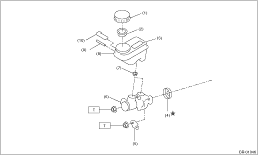
(1) | Cap - reservoir tank | (6) | Cylinder body ASSY | Tightening torque: N·m (kgf-m, ft-lb) | |
(2) | Filter - master cylinder | (7) | Seal | T: | 13 (1.33, 9.6) |
(3) | Caution label (model with caution label) | (8) | Reservoir tank | ||
(4) | Seal sub ASSY | (9) | Pin | ||
(5) | Bracket - master cylinder | (10) | Level - indicator | ||
4. FRONT BRAKE PIPES AND HOSES
• Models without EyeSight
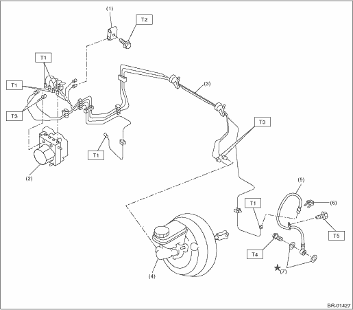
(1) | Connector - two-way | (5) | Front brake hose RH/LH | Tightening torque: N·m (kgf-m, ft-lb) | |
(2) | VDC control module and hydraulic control unit (VDCCM&H/U) | (6) | Clamp | T1: | 15 (1.53, 11.1) |
(3) | Front brake pipe ASSY | (7) | Gasket | T2: | 18 (1.84, 13.3) |
(4) | Master cylinder ASSY | T3: | 19 (1.94, 14.0) | ||
T4: | 26 (2.65, 19.2) | ||||
T5: | 33 (3.36, 24.3) | ||||
• Models with EyeSight
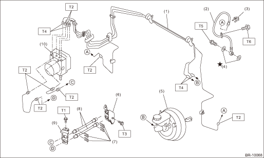
(1) | Front brake pipe ASSY | (7) | Clamp | Tightening torque: N·m (kgf-m, ft-lb) | |
(2) | Front brake hose RH/LH | (8) | Brake hose ASSY | T1: | 7.5 (0.76, 5.5) |
(3) | Clamp | (9) | Bracket | T2: | 15 (1.53, 11.1) |
(4) | Gasket | (10) | VDC control module and hydraulic control unit (VDCCM&H/U) | T3: | 18 (1.84, 13.3) |
(5) | Master cylinder ASSY | T4: | 19 (1.94, 14.0) | ||
(6) | Bracket | T5: | 26 (2.65, 19.2) | ||
T6: | 33 (3.36, 24.3) | ||||
5. CENTER AND REAR BRAKE PIPES AND HOSES
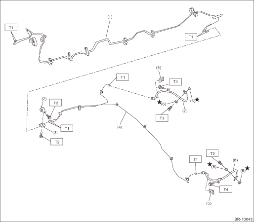
(1) | Center brake pipe ASSY | (5) | Clamp | Tightening torque: N·m (kgf-m, ft-lb) | |
(2) | Bracket | (6) | Gasket | T1: | 15 (1.53, 11.1) |
(3) | Connector | (7) | Rear brake hose RH | T2: | 18 (1.84, 13.3) |
(4) | Rear brake pipe ASSY | (8) | Rear brake hose LH | T3: | 26 (2.65, 19.2) |
T4: | 33 (3.4, 24.3) | ||||
6. BRAKE BOOSTER
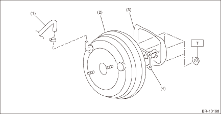
(1) | Vacuum hose | (3) | Damping seat (model with EyeSight) | Tightening torque: N·m (kgf-m, ft-lb) | |
(2) | Vacuum booster ASSY | (4) | Gasket | T: | 18 (1.84, 13.3) |
7. BRAKE PEDAL
• CVT model
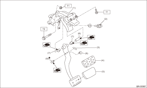
(1) | Brake pedal ASSY | (6) | Spacer - pedal | Tightening torque: N·m (kgf-m, ft-lb) | |
(2) | Stop light switch | (7) | Bushing - pedal | T1: | 18 (1.84, 13.3) |
(3) | Snap pin | (8) | Stopper - pedal | T2: | 30 (3.06, 22.1) |
(4) | Pad - brake pedal (sport type) | (9) | Clevis pin | ||
(5) | Pad - brake pedal (normal type) | ||||
• MT model
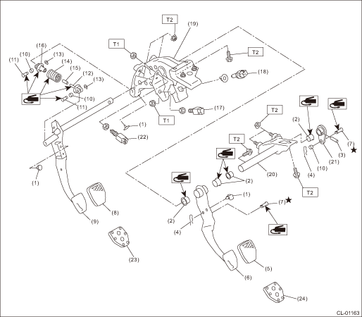
(1) | Stopper | (11) | Clutch clevis pin | (21) | Lever |
(2) | Bushing | (12) | Assist rod A | (22) | Clutch start switch |
(3) | Spring pin | (13) | Clip | (23) | Pad - clutch pedal (sport type) |
(4) | Snap pin | (14) | Assist spring | (24) | Pad - brake pedal (sport type) |
(5) | Pad - brake pedal (normal type) | (15) | Assist bushing | ||
(6) | Brake pedal | (16) | Assist rod B | Tightening torque: N·m (kgf-m, ft-lb) | |
(7) | Clevis pin | (17) | Clutch switch | T1: | 8 (0.8, 5.9) |
(8) | Pad - clutch pedal (normal type) | (18) | Stop light switch | T2: | 18 (1.8, 13.3) |
(9) | Clutch pedal | (19) | Pedal bracket | ||
(10) | Bushing C | (20) | Clutch master cylinder bracket | ||
 Specification
BRAKE > General DescriptionSPECIFICATIONNOTE:Refer to “PARKING BRAKE” for parking brake specifications. General Description > SPECIFICATION">1. FRONT DISC BRAKEItemSpecifica ...
 Master cylinder
...
Other materials:
Telltale screen
Telltale screen
When specific conditions or system states occur in the Subaru Ascent, corresponding
telltale indicators are displayed on this screen to notify the driver. These indicators
provide immediate visual feedback regarding vehicle status and potential issues.
NOTE
When mu ...
Inspection
STARTING/CHARGING SYSTEMS(H4DO) > BatteryINSPECTIONWARNING:• As batteries produce flammable gases, be careful not to bring an open flame close to the batteries.• Ventilate sufficiently when using or charging battery in enclosed space.• Electrolyte is corrosive acid, and has toxi ...
Dtc b28b7 ldp off switch
EyeSight (DIAGNOSTICS) > Diagnostic Procedure with Diagnostic Trouble Code (DTC)DTC B28B7 LDP OFF SWITCHDetected when lane departure warning OFF switch circuit is not installed, open-circuited, or is stuck to ON.DTC detecting condition:• Wiring of lane departure warning OFF switch is not co ...
