Subaru Crosstrek Service Manual: Check eyesight steering switch
EyeSight (DIAGNOSTICS) > Diagnostics with Phenomenon
CHECK EyeSight STEERING SWITCH
Trouble symptom:
• Cruise control cannot be set. (Cancelled immediately.)
• Cruise control cannot be released.
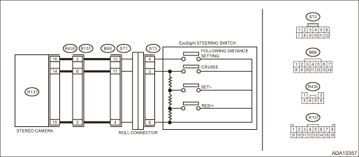
Wiring diagram:
EyeSight System EyeSight System > WIRING DIAGRAM">
| STEP | CHECK | YES | NO |
1.CHECK EyeSight STEERING SWITCH CIRCUIT.
1) Remove the driver’s airbag module. Driver’s Airbag Module > REMOVAL">
2) Disconnect the EyeSight steering switch harness connector.
3) Turn the ignition switch to ON.
4) Measure the voltage between harness connector terminal and chassis ground.
Connector & terminal
(ST3) No. 3 (+) — Chassis ground (−):
(ST3) No. 4 (+) — Chassis ground (−):
Is the voltage 5 V or more?
Diagnostics with Phenomenon > CHECK EyeSight STEERING SWITCH">Go to Step 2.
Check for open/short circuit or poor contact in the harness between EyeSight steering switch and ECM and in the steering roll connector.
2.CHECK EyeSight STEERING SWITCH CIRCUIT.
1) Turn the ignition switch to OFF.
2) Remove the EyeSight steering switch. Switches and Harness">
3) Measure the resistance between harness connector terminal and chassis ground.
Connector & terminal
(ST3) No. 9 — Chassis ground:
Is the resistance less than 10 ??
Diagnostics with Phenomenon > CHECK EyeSight STEERING SWITCH">Go to Step 3.
Check for open circuit between EyeSight steering switch and chassis ground.
3.CHECK EyeSight STEERING SWITCH.
Check EyeSight steering switch. Switches and Harness">
Is the EyeSight steering switch normal?
Replace the ECM. Engine Control Module (ECM) > REMOVAL">
Replace the EyeSight steering switch. Switches and Harness">

 Diagnostic procedure with phenomenon
EyeSight (DIAGNOSTICS) > Diagnostics with PhenomenonDIAGNOSTIC PROCEDURE WITH PHENOMENON1. TEMPORARY STOP OF EyeSightPhenomenonCheck ItemReference1Temporary stop occurs frequently.EyeSight temporar ...
Other materials:
Removal
ENTERTAINMENT > AudioREMOVALCAUTION:Before handling the airbag system components, refer to “CAUTION” of “General Description” in “AIRBAG SYSTEM”. General Description > CAUTION">1. Disconnect the ground cable from battery and wait for at least 60 sec ...
Removal
LIGHTING SYSTEM > High-mounted Stop LightREMOVAL1. CROSSTREK MODEL1. Disconnect the ground cable from battery. NOTE">2. Remove the trim panel - rear gate UPR. Rear Gate Trim > REMOVAL">3. Remove the light assembly - high-mounted.(1) Remove the nut.(2) From the inside of the r ...
Inspection
CONTINUOUSLY VARIABLE TRANSMISSION(TR580) > Reverse Brake AssemblyINSPECTION• Inspect the drive plate facing for wear and damage.• Check the driven plate for discoloration (burnt color).• Check for worn snap ring, fatigue or damaged return spring or deformed spring retainer.&bul ...
