Subaru Crosstrek Service Manual: Brake line Inspection
PERIODIC MAINTENANCE SERVICES > Brake Line
INSPECTION
1. BRAKE LINE
1. Check for scratches, swelling, corrosion, traces of fluid leakage on the brake hoses or pipe joints.
2. Make sure that brake pipes/hoses do not interfere with adjacent parts and there is no loose connector/clamp during driving.
3. Check any trace of fluid leakage, scratches, etc. on master cylinder, wheel cylinder and hydraulic unit.
NOTE:
• When the brake fluid level in the reservoir tank is lower than specified limit, the brake warning light on the combination meter will illuminate.
• Visually check the brake hose for damage. (Use a mirror where it is difficult to see)
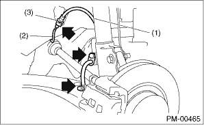
(1) | Front brake hose |
(2) | Front brake pipe |
(3) | Clamp |
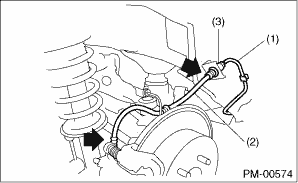
(1) | Brake pipe |
(2) | Rear brake hose |
(3) | Clamp |
2. SERVICE BRAKE
Refer to “BR” section for foot brake inspection. Brake Pedal > INSPECTION">
3. BRAKE SERVO SYSTEM
1. With the engine off, depress the brake pedal several times applying the same pedal force. Check that the travel distance should not change.
2. With the brake pedal depressed, start the engine. Check that the pedal moves slightly toward the floor.
3. With the brake pedal depressed, stop the engine and keep the pedal depressed for 30 seconds. Check that the pedal height does not change.
4. A check valve is built into the brake booster nipple. Disconnect the vacuum hose to inspect function of check valve.
Check that check valve ventilates from booster side to engine side. Also, check that there is no ventilation from engine side to booster side.
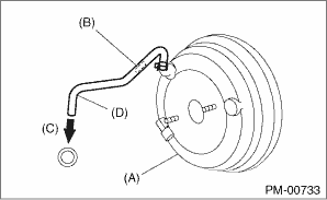
(A) | Brake booster |
(B) | Check valve |
(C) | Engine side |
(D) | Vacuum hose |
5. Check the vacuum hose for cracks or other damage.
CAUTION:
When installing the vacuum hose on the engine and brake booster, do not use soapy water or lubricating oil on their connections.
6. Check that the vacuum hose is securely tightened.
 Axle boots joints Inspection
PERIODIC MAINTENANCE SERVICES > Axle Boots & JointsINSPECTION1. FRONT AND REAR AXLE BOOTSInspect the front axle boots (A) and rear axle boots (B) for deformation, damage or failure. If faulty, ...
 Clutch system Inspection and adjustment
PERIODIC MAINTENANCE SERVICES > Clutch SystemINSPECTION AND ADJUSTMENTRefer to “CL” section for inspection and adjustment of clutch system. Clutch Pedal > INSPECTION"> Clut ...
Other materials:
Removal
GLASS/WINDOWS/MIRRORS > Windshield GlassREMOVAL1. USING WINDSHIELD GLASS KNIFECAUTION:• For model with EyeSight, always remove the glass - front window after the stereo camera is removed.• For model with EyeSight, always use Subaru genuine windshield glass specially designed for EyeSi ...
Installation
CLUTCH SYSTEM > Clutch Disc and CoverINSTALLATION1. Insert the ST into the clutch disc and the ST end into pilot bearing to install the clutch disc.NOTE:When installing the clutch disc, be careful to attach in the correct direction.ST 499747100CLUTCH DISC GUIDE(A)Flywheel side2. Install the cl ...
Dtc b1578 meter
IMMOBILIZER (DIAGNOSTICS) > Diagnostic Procedure with Diagnostic Trouble Code (DTC)DTC B1578 METERDTC DETECTING CONDITION:• Except for C5 modelReference code incompatibility between combination meter and body integrated unit or communication failure between body integrated unit and ECM&bull ...
