Subaru Crosstrek Service Manual: Assembly
STARTING/CHARGING SYSTEMS(H4DO) > Generator
ASSEMBLY
Assemble in the reverse order of disassembly.
NOTE:
• Refer to component for tightening torque of each part. General Description > COMPONENT">
• After assembling, manually turn the pulley to check that the rotor rotates smoothly.
1. Assembling the rear cover and rectifier
Remove old silicone grease on the mating surface of rear cover and rectifier and apply new silicone grease.
CAUTION:
Do not apply silicone grease to the attachment threads of rectifier.
2. Push of the brush
Before assembling the front and rear parts, press the brush down into the brush holder, then fix the brush in that position by inserting a [1 mm (0.0394 in) dia., 40 — 50 mm (1.5748 — 1.9685 in) long] wire through the hole as shown in the figure.
CAUTION:
After assembling, remove the wire.
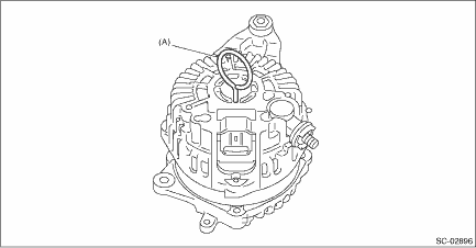
(A) | Wire |
3. Install the ball bearings.
(1) Set the ball bearings in the front cover, then securely install an appropriate tool (such as a socket wrench of proper size) to the bearing outer race.
(2) Using a press to press the ball bearings into the specified location.
(3) Install the bearing retainer.
4. Install the bearings.
CAUTION:
Do not apply grease to the bearings. If there is any oil on the bearing box, remove it completely.
(1) Use a press to install the bearings to the rotor shaft.
(2) Heat the bearing box in rear cover at 50 to 60°C (122 to 140°F), and then press the bearing into rear cover.
 Generator
...
 Removal
STARTING/CHARGING SYSTEMS(H4DO) > GeneratorREMOVAL1. Remove the V-belt covers.2. Disconnect the ground cable from battery. NOTE">3. Remove the V-belts. V-belt > REMOVAL">4. Dis ...
Other materials:
Dtc c2223 transmitter 3 pressure data abnormal
TIRE PRESSURE MONITORING SYSTEM (DIAGNOSTICS) > Diagnostic Procedure with Diagnostic Trouble Code (DTC)DTC C2223 TRANSMITTER 3 PRESSURE DATA ABNORMALNOTE:Refer to DTC C2224 for diagnostic procedure. Diagnostic Procedure with Diagnostic Trouble Code (DTC) > DTC C2224 TRANSMITTER 4 PRESSURE DAT ...
Installation
WIPER AND WASHER SYSTEMS > Front Wiper Motor and LinkINSTALLATIONCAUTION:• If the cowl panel assembly cannot be installed properly, do not hit or set it forcibly. The claws of the cowl panel or the windshield glass may be damaged.• Before installing the windshield glass and cowl panel ...
Location
EyeSight > Relay and FuseLOCATIONRelay & fuse boxFuse 10 A (stop light and brake switch, brake light relay)(A)Relay holderBrake light relay(B)NOTE:For other related fuses, refer to the wiring diagram. Power Supply Circuit"> ...
