Subaru Crosstrek Service Manual: Assembly
BRAKE > Front Disc Brake Assembly
ASSEMBLY
1. Before assembly, check each part. Front Disc Brake Assembly > INSPECTION">
2. Clean the inside of the caliper body cylinder using brake fluid.
3. Apply a coat of brake fluid to piston seal and install the piston seal to the caliper body cylinder groove.
4. Apply a coat of brake fluid to the inner surface of caliper body cylinder and the entire outer surface of the piston - disc brake.
5. Apply grease contained in the piston seal kit to the piston boot, and install it to the groove at the end of the cylinder.
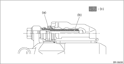
6. Insert the piston - disc brake into the caliper body cylinder.
7. Position the piston boot in the grooves on the piston - disc brake and the caliper body cylinder.
CAUTION:
Do not force the piston - disc brake into the caliper body cylinder.

(a) | Piston - disc brake | (c) | Caliper body assembly | (d) | Piston seal |
(b) | Piston boot |
8. Apply grease contained in the piston seal kit to the lock pin - front brake, the outer surface of guide pin - front brake, the inner surface of support cylinder, and the grooves of pin boot.
9. Install the pin boot to the lock pin - front brake and guide pin - front brake, and insert them into the support cylinder.
CAUTION:
Insert the lock pin - front brake and guide pin - front brake into specified position, and make sure that they slide and seat properly.
(a) | Pin boot | (b) | Lock pin - front brake or guide pin - front brake | (c) | Grease applied area |

 Removal
BRAKE > Front Disc Brake AssemblyREMOVALCAUTION:Do not allow brake fluid to come in contact with the painted surface of the vehicle body. If it does, wash off with water and wipe away completely.1. ...
Other materials:
Selecting audible signal operation
The Subaru Ascent provides audible confirmation (electronic chirps) when locking
or unlocking the vehicle. This feature can be customized or disabled through the
center information display according to user preference.
Additionally, the volume level of the Subaru Ascent audible signal can be ad ...
Dtc c1331 rr hold valve
VEHICLE DYNAMICS CONTROL (VDC) (DIAGNOSTICS) > Diagnostic Procedure with Diagnostic Trouble Code (DTC)DTC C1331 RR HOLD VALVENOTE:For the diagnostic procedure, refer to “DTC C1362 NORMAL CLOSING VALVE 2”. Diagnostic Procedure with Diagnostic Trouble Code (DTC) > DTC C1362 NORMAL C ...
Installation
HVAC SYSTEM (HEATER, VENTILATOR AND A/C) > Heater Vent DuctINSTALLATIONCAUTION:Before handling the airbag system components, refer to “CAUTION” of “General Description” in “AIRBAG SYSTEM”. General Description > CAUTION">Install each part in the reve ...
