Subaru Crosstrek Service Manual: Adjustment
PARKING BRAKE > Parking Brake Assembly (Rear Disc Brake)
ADJUSTMENT
1. SHOE CLEARANCE
1. Return the lever assembly - hand brake completely.
2. Loosen the adjusting nut, and make the cable free.
3. Remove the adjusting hole cover (A) from the rear disc rotor.
4. Insert a flat tip screwdriver (b) into the adjustment hole, and rotate the adjuster assembly - rear brake (a) until the disc rotor cannot be turned by hand.
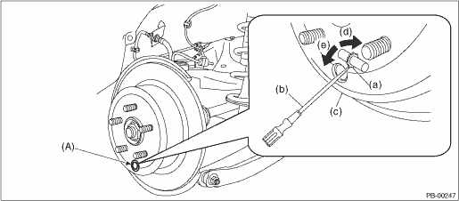
(a) | Adjuster ASSY - rear brake | (c) | Disc rotor | (e) | Shorten the adjuster ASSY - rear brake |
(b) | Flat tip screwdriver | (d) | Extend the adjuster ASSY - rear brake |
5. Loosen the adjuster assembly - rear brake by 10 notches in the direction of the arrow (e).
CAUTION:
• Check there is no brake drag.
• Make sure that the adjuster assembly - rear brake is loosened by 10 notches. If it is not loosened sufficiently, dragging may occur.
6. Install the adjusting hole cover to the disc rotor.
7. Adjust the parking lever stroke. Parking Brake Assembly (Rear Disc Brake) > ADJUSTMENT">
2. LEVER STROKE
1. Adjust the shoe clearance before adjusting lever stroke. Parking Brake Assembly (Rear Disc Brake) > ADJUSTMENT">
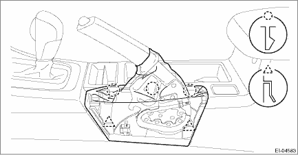
2. Release the claws, and then remove the boot - parking brake.
3. Pull the lever assembly - hand brake hard 3 to 5 times.
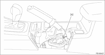
4. Turn the adjusting nut (a) until the lever stroke is at the specified value.
Lever stroke:
7 to 8 notches when pulled with a force of 200 N (20.4 kgf, 45 lbf)
5. Check there is no brake drag.
6. Check that the brake warning light illuminates when the lever assembly - hand brake is operated.
NOTE:
The light must illuminate when the first notch is reached after pulling the lever.
7. Install the boot - parking brake.

 Removal
PARKING BRAKE > Parking Brake Assembly (Rear Disc Brake)REMOVAL1. Release the parking brake.2. Lift up the vehicle, and then remove the rear wheels.3. Remove the rear disc rotor. Rear Disc Rotor & ...
Other materials:
Dtc b2301 rear radar circuit high
Blind Spot Detection/Rear Cross Traffic Alert (DIAGNOSTICS) > Diagnostic Procedure with Diagnostic Trouble Code (DTC)DTC B2301 REAR RADAR CIRCUIT HIGHDTC detecting condition:• Open circuit or short circuit to power supply in harness between radar sensor and outer mirror assembly.• Ope ...
Dtc c0049 cruise controller abnormal
VEHICLE DYNAMICS CONTROL (VDC) (DIAGNOSTICS) > Diagnostic Procedure with Diagnostic Trouble Code (DTC)DTC C0049 CRUISE CONTROLLER ABNORMALDTC detecting condition:Faulty signal is received from the stereo camera.Trouble symptom:• VDC may not operate.• EyeSight does not operate.STEPCHEC ...
Replacement
MANUAL TRANSMISSION AND DIFFERENTIAL(5MT) > Oil SealREPLACEMENT1. Disconnect the ground cable from battery.2. Lift up the vehicle.3. Clean the transmission exterior.4. Using the TORX® bit T70, remove the drain plug, and drain the transmission gear oil completely.CAUTION:• Immediately after ...
