Subaru Crosstrek Service Manual: Adjustment
LIGHTING SYSTEM > Headlight Assembly
ADJUSTMENT
1. HEADLIGHT BEAM ADJUSTMENT
CAUTION:
• Turn off the light before adjusting the beam level of the light assembly - head. If it is necessary to inspect the beam level, do not keep the light on for two minutes or more.
• When blocking the light emitted from the headlight, use a light shield or equivalent.
Do not apply the tape on the lens or place the cloth over it. It may raise the temperature in the light and cause deformation/bubble formations of the plastic lens.
1. Before checking the beam level of the light assembly - head, be sure of the following:
• The area around the light assembly - head has not sustained any scratches, damage or other type of deformation.
• The vehicle is parked on a level surface.
• The inflation pressure of tires is correct.
• The vehicle does not have load.
• Vehicle’s fuel tank is fully filled.
2. Bounce the vehicle several times to normalize the suspension.
3. Make certain that someone is seated in the driver’s seat.
4. Measure the distance between the low beam bulb centers and the height of the bulb center.
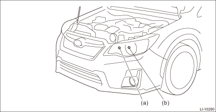
(a) | High beam | (b) | Low beam |
5. Adjust the beam level of the light assembly - head (low beam).
(1) Place the vehicle with the front end facing to the measurement panel, then illuminate the low beam.
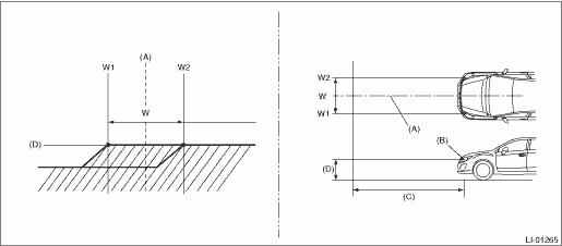
(A) | Vehicle center | (C) | 3 m (10 ft) | (D) | Height of headlight center |
(B) | Bulb center marking |
W mm (in) |
1,281 (50.44) |
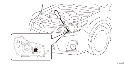
(2) Adjust the low beam by turning the aiming screw.

 Removal
LIGHTING SYSTEM > Headlight AssemblyREMOVALCAUTION:• Do not perform work with wet hands, because there is a possibility of electrical shock.• The HID type uses very high voltages for th ...
Other materials:
Dtc p1494 coil 2 egr "a" control circuit low
ENGINE (DIAGNOSTICS)(H4DO) > Diagnostic Procedure with Diagnostic Trouble Code (DTC)DTC P1494 COIL 2 EGR "A" CONTROL CIRCUIT LOWNOTE:For the diagnostic procedure, refer to DTC P1498. Diagnostic Procedure with Diagnostic Trouble Code (DTC) > DTC P1498 COIL 4 EGR "A" CONTROL ...
Operation during cold weather
Maintenance
When operating your Subaru Ascent in winter conditions, proper preparation is
essential for safety and reliability. It is highly recommended to carry emergency
supplies such as an ice scraper, sand for traction, warning flares, a compact shovel,
and jumper cables to handle unexpec ...
Adjustment
VEHICLE DYNAMICS CONTROL (VDC) > VDC Control Module and Hydraulic Control Unit (VDCCM&H/U)ADJUSTMENT1. VDC SENSOR MIDPOINT SETTING MODE (MODELS WITHOUT EyeSight)After installing, replacing or adjusting the following parts, perform the VDC sensor midpoint setting mode.• Steering angle se ...
