
Subaru Crosstrek Service Manual: Adjustment
EXTERIOR BODY PANELS > Rear Gate
ADJUSTMENT
Adjust the clearance around the panel - rear gate as follows.
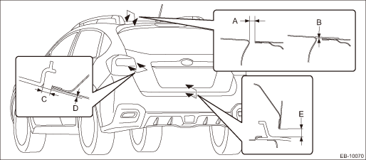
Part | Standard | |
A | Panel - rear gate to Roof panel | 6.0+1.0, −0.5 mm (0.24+0.04, −0.02 in) |
B | Surface level gap: Panel - rear gate to Roof panel | 1.0±1.0 mm (0.04±0.04 in) |
C | Panel - rear gate to Light assembly - rear combination | 6.0±1.0 mm (0.24±0.04 in) |
D | Surface level gap: Panel - rear gate to Light assembly - rear combination | 1.0±1.0 mm (0.04±0.04 in) |
E | Panel - rear gate to Bumper face - rear | 8.0±1.5 mm (0.31±0.06 in) |
1. Adjust the vertical and horizontal positions of the panel - rear gate.
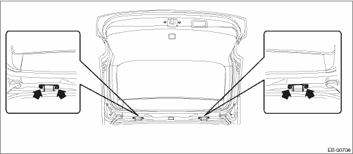
(1) Loosen the mounting bolts of the hinge - rear gate.
(2) Adjust the vertical and horizontal clearance of the panel - rear gate.
Tightening torque:
25 N·m (2.55 kgf-m, 18.4 ft-lb)
2. Adjust the surface level gap between the panel - rear gate and the body.
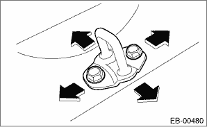
(1) Remove the trim panel - rear skirt.
(2) Loosen the bolt.
(3) Tap the striker - rear gate using a plastic hammer to adjust the surface level gap between the panel - rear gate and the body.
Tightening torque:
25 N·m (2.55 kgf-m, 18.4 ft-lb)
 Rear gate
...
 Removal
EXTERIOR BODY PANELS > Rear GateREMOVALCAUTION:The panel - rear gate is heavy. When removing and installing it, always work in a team of two or more persons.1. REAR GATE PANEL1. Disconnect the grou ...
Other materials:
Removal
LIGHTING SYSTEM > Rear Height SensorREMOVALCAUTION:Always remove the sensor assembly - headlight beam leveler before removing any parts related to the suspension.1. Disconnect the ground cable from battery. NOTE">2. Lift up the vehicle, and remove the left rear wheel.3. Remove the sensor ...
Removal
MANUAL TRANSMISSION AND DIFFERENTIAL(5MT) > Main Shaft AssemblyREMOVAL1. Remove the manual transmission assembly from the vehicle. Manual Transmission Assembly > REMOVAL">2. Remove the transfer case together with the extension case assembly. Transfer Case and Extension Case Assembly ...
Electrical specification
POWER ASSISTED SYSTEM (POWER STEERING) (DIAGNOSTICS) > Control Module I/O SignalELECTRICAL SPECIFICATIONNOTE:The terminal numbers of the power steering control module connectors are as indicated in the figure.ContentsTerminal No.Input/output signalMeasured value and measuring conditionsPower supp ...
