Subaru Crosstrek Service Manual: Adjustment
CONTINUOUSLY VARIABLE TRANSMISSION(TR580) > Reduction Drive Gear
ADJUSTMENT
1. Remove the retaining springs and reduction drive gear shims.
2. Install the transmission case, and secure it with four or five bolts.
Tightening torque:
22 N·m (2.2 kgf-m, 16.2 ft-lb)
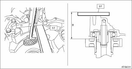
3. Measure depth “A” from the ST upper face to the reduction drive gear end face.
| ST 499575400 | GAUGE |

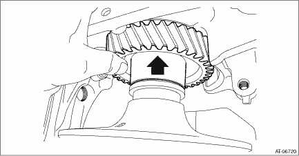
4. Raise and hold the reduction drive gear.

5. Measure depth “B” from the ST upper face to the reduction drive gear end face.
| ST 499575400 | GAUGE |

6. Calculate the following formula.
T mm = A − B − 1.0
[T in = A − B − 0.039]
T: Moving distance of reduction drive gear shim
A: Depth from the ST upper face to the reduction drive gear end surface
B: Depth from the ST upper face to the reduction drive gear end surface
1.0 mm (0.039 in): Thickness of spring retainer
Moving distance of transfer drive gear [T] | Total shim thickness mm (in) |
0.420 — 0.519 (0.0165 — 0.0204) | 0.3 (0.012) |
0.520 — 0.619 (0.0205 — 0.0242) | 0.4 (0.016) |
0.620 — 0.719 (0.0244 — 0.0283) | 0.5 (0.020) |
0.720 — 0.819 (0.0283 — 0.0322) | 0.6 (0.024) |
0.820 — 0.919 (0.0323 — 0.0362) | 0.7 (0.028) |
0.920 — 1.019 (0.0362 — 0.0401) | 0.8 (0.031) |
1.020 — 1.119 (0.0402 — 0.0441) | 0.9 (0.035) |
1.120 — 1.219 (0.0441 — 0.0480) | 1.0 (0.039) |
1.220 — 1.319 (0.0480 — 0.0519) | 1.1 (0.043) |
1.320 — 1.419 (0.0520 — 0.0559) | 1.2 (0.047) |
1.420 — 1.519 (0.0559 — 0.0598) | 1.3 (0.051) |
1.520 — 1.619 (0.0598 — 0.0637) | 1.4 (0.055) |
1.620 — 1.719 (0.0638 — 0.0677) | 1.5 (0.059) |
1.720 — 1.819 (0.0677 — 0.0716) | 1.6 (0.063) |
1.820 — 1.920 (0.0717 — 0.0756) | 1.7 (0.067) |
7. Select one to three reduction drive gear shims so that the total thickness meets the value obtained from step 6).
Part No. | Reduction drive gear shim thickness mm (in) |
31288AA260 | 0.3 (0.012) |
31288AA270 | 0.4 (0.016) |
31288AA280 | 0.5 (0.020) |
31288AA290 | 0.6 (0.024) |
 Removal
CONTINUOUSLY VARIABLE TRANSMISSION(TR580) > Reduction Drive GearREMOVAL1. Remove the transmission assembly from the vehicle. Automatic Transmission Assembly > REMOVAL">2. Remove the air ...
Other materials:
Removal
HVAC SYSTEM (HEATER, VENTILATOR AND A/C) > CondenserREMOVAL1. Using the refrigerant recovery system, discharge refrigerant. Refrigerant Recovery Procedure > PROCEDURE">2. Remove the air intake duct. Air Intake Duct > REMOVAL">3. Remove the clip, and remove the bracket - gr ...
Removal
FUEL INJECTION (FUEL SYSTEMS)(H4DO) > Engine Control Module (ECM)REMOVAL1. Disconnect the ground cable from battery.2. Remove the glove box. Glove Box > REMOVAL">3. Disconnect the connector from ECM.4. Remove the bolts and nuts, and remove the ECM. ...
Dtc b2814 power supply low voltage
EyeSight (DIAGNOSTICS) > Diagnostic Procedure with Diagnostic Trouble Code (DTC)DTC B2814 POWER SUPPLY LOW VOLTAGEDetected when the status of 7.0 V or less continues approximately for 5 seconds and is judged to be low-voltage malfunction, or when the +B harness of the stereo camera is broken.DTC ...

