Subaru Crosstrek Service Manual: Adjustment
CLUTCH SYSTEM > Clutch Switch
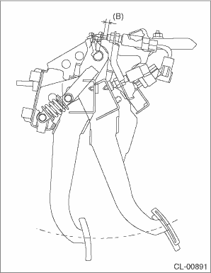
ADJUSTMENT
1. Loosen the lock nut of the clutch start switch.
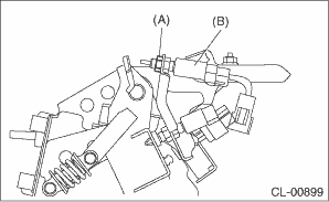
(A) | Lock nut |
(B) | Clutch start switch |
2. Disconnect the harness connector of the clutch start switch.
3. Remove the snap pin and clevis pin connecting the clutch pedal and operating rod.
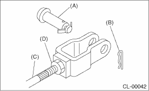
(A) | Clevis pin |
(B) | Snap pin |
(C) | Push rod |
(D) | Lock nut |
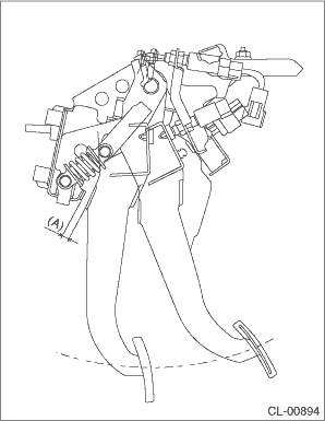
4. Adjust the clutch start switch so that the switch turns on when the clearance between clutch pedal stopper and clutch pedal is within the specification described below, and then tighten the lock nut.
Clearance A:
6.3 — 8.6 mm (0.25 — 0.34 in)
Tightening torque:
8 N·m (0.8 kgf-m, 5.9 ft-lb)
NOTE:
• Using a plate of the same thickness for the clearance facilitates the adjustment operation.
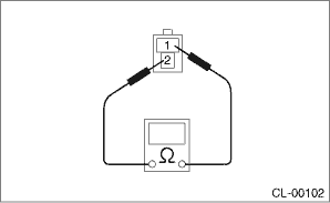
• Using the Subaru Select Monitor or a tester, check the position where the switch turns on.
Check the following figure for the terminal layout of the harness connector.
• When performing adjustment by the clearance between clutch start switch and clutch pedal plate, perform installation according to the following gap.
Clearance B:
8.6 — 9.0 mm (0.34 — 0.35 in)
5. Connect the clutch start switch connector.
 Clutch switch
...
 Removal
CLUTCH SYSTEM > Clutch SwitchREMOVALCAUTION:Before handling the airbag system components, refer to “CAUTION” of “General Description” in “AIRBAG SYSTEM”. Genera ...
Other materials:
Removal
SECURITY AND LOCKS > Access BuzzerREMOVAL1. Disconnect the ground cable from battery. NOTE">2. Lift up the vehicle.3. Remove the clips and screws, and turn over the front side of the mud guard - front RH.4. Remove the access buzzer.(1) Disconnect the connector.(2) Remove the clip and det ...
Operation
HI - Rapid heating
LO - Normal heating
Off
Left-hand side
Right-hand side
To turn on the seat heater, push the "LO"
or "HI" position on the switch, as desired,
depending on the temperature.
Selecting the "HI" position will cause the
seat to heat up quicker.
To turn off ...
Dtc c0057 ecm control system
VEHICLE DYNAMICS CONTROL (VDC) (DIAGNOSTICS) > Diagnostic Procedure with Diagnostic Trouble Code (DTC)DTC C0057 ECM CONTROL SYSTEMDTC detecting condition:ECM malfunctioningTrouble symptom:• VDC does not operate.• EyeSight does not operate.STEPCHECKYESNO1.CHECK COOPERATION CONTROL FEAS ...
