Subaru Crosstrek Service Manual: 11
CRUISE CONTROL SYSTEM (DIAGNOSTICS) > Diagnostic Procedure with Cancel Code
11
When CRUISE switch is pressed, or a malfunction related to CRUISE switch occurs, this is detected.
Trouble symptom:
• Cruise control cannot be set. (Cancelled immediately.)
• Cruise control cannot be released.
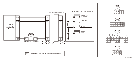
Wiring diagram:
Cruise control system Cruise Control System > WIRING DIAGRAM">
| STEP | CHECK | YES | NO |
1.CHECK CRUISE CONTROL COMMAND SWITCH CIRCUIT.
1) Remove the driver’s airbag module. Driver’s Airbag Module > REMOVAL">
2) Disconnect the harness connector of cruise control command switch.
3) Turn the ignition switch to ON.
4) Measure the voltage between harness connector terminal and chassis ground.
Connector & terminal
(ST3) No. 4 (+) — Chassis ground (−):
(ST3) No. 3 (+) — Chassis ground (−):
Is the voltage 5 V or more?
Diagnostic Procedure with Cancel Code > 11">Go to Step 2.
Check the harness between cruise control command switch and ECM, and the steering roll connector for open or short circuit, or for poor contact.
2.CHECK CRUISE CONTROL COMMAND SWITCH CIRCUIT.
1) Turn the ignition switch to OFF.
2) Remove the cruise control command switch. Cruise Control Command Switch > REMOVAL">
3) Measure the resistance between harness connector terminal and chassis ground.
Connector & terminal
(ST3) No. 9 — Chassis ground:
Is the resistance less than 10 ??
Diagnostic Procedure with Cancel Code > 11">Go to Step 3.
Check for open circuit between cruise control command switch, ECM, and chassis ground and check the ECM.
3.CHECK CRUISE CONTROL COMMAND SWITCH.
Measure the resistance between switch terminals when the cruise control command switch is not depressed.
Terminals
No. 3 — No. 9:
Is the resistance approx. 4 k??
Diagnostic Procedure with Cancel Code > 11">Go to Step 4.
Replace the cruise control command switch.
Cruise Control Command Switch">
4.CHECK CANCEL SWITCH.
1) Turn the ignition switch to OFF.
2) Remove the cruise control command switch. Cruise Control Command Switch > REMOVAL">
3) Measure the resistance between switch terminals with the CANCEL switch pressed.
Terminals
No. 3 — No. 9:
Is the resistance approx. less than 1 ? when the CANCEL switch is pressed?
Diagnostic Procedure with Cancel Code > 11">Go to Step 5.
Replace the cruise control command switch.
Cruise Control Command Switch">
5.CHECK SET/− SWITCH.
Measure the resistance between the switch terminals with the SET/− switch pressed.
Terminals
No. 3 — No. 9:
Is the resistance approx. 250 ? when the SET/− switch is pressed?
Diagnostic Procedure with Cancel Code > 11">Go to Step 6.
Replace the cruise control command switch. Cruise Control Command Switch">
6.CHECK RES/+ SWITCH CIRCUIT.
Measure the resistance between the switch terminals with the RES/+ switch pressed.
Terminals
No. 3 — No. 9:
Is the resistance approx. 1,500 ? when the RES/+ switch is pressed?
Replace the ECM.
Engine Control Module (ECM)">
Replace the cruise control command switch. Cruise Control Command Switch">

 49
49
CRUISE CONTROL SYSTEM (DIAGNOSTICS) > Diagnostic Procedure with Cancel Code49Automatic transmission malfunction is detected.Automatic transmission malfunction is detected during cruise driving or c ...
Other materials:
Welcome screen
When the door is unlocked and the
driver's door is opened, the welcome
screen will appear for a short time.
NOTE
The welcome screen will disappear
when the ignition switch is turned to
the "ON" position while the welcome
screen is displayed.
If any of the doors (including the
re ...
Installation
FRONT SUSPENSION > Front StabilizerINSTALLATION1. Before installation, inspect the following items and replace any faulty part with a new one.• Check the bushing - stabilizer for abnormal cracks, fatigue or damage.• Check the stabilizer link for damage.2. Install each part in the reve ...
Electrical specification
KEYLESS ACCESS WITH PUSH BUTTON START SYSTEM (DIAGNOSTICS) > Control Module I/O SignalELECTRICAL SPECIFICATION1. KEYLESS ACCESS CMTerminal No.Terminal symbolContent(B572) No. 2+B+B(B572) No. 3INDSStart switch indicator (green) output(B572) No. 5N-SWNeutral switch input(B572) No. 7STSWSTSW output( ...
