Subaru Crosstrek Service Manual: Steering angle sensor Replacement
VEHICLE DYNAMICS CONTROL (VDC) > Steering Angle Sensor
REPLACEMENT
CAUTION:
• If the steering wheel and steering angle sensor are removed, perform the following VDC setting mode.
– Model without EyeSight: VDC sensor midpoint setting mode VDC Control Module and Hydraulic Control Unit (VDCCM&H/U) > ADJUSTMENT">
– Model with EyeSight: Neutral of Steering Angle Sensor & Lateral G Sensor 0 point setting mode VDC Control Module and Hydraulic Control Unit (VDCCM&H/U) > ADJUSTMENT">
– Model with EyeSight: Longitudinal G sensor & lateral G sensor 0 point setting mode VDC Control Module and Hydraulic Control Unit (VDCCM&H/U) > ADJUSTMENT">
• Before handling the airbag system components, always refer to “CAUTION” of “General Description” in “AIRBAG SYSTEM”. General Description > CAUTION">
• Always use the steering wheel puller for removal to avoid deforming the steering wheel.
• If the steering wheel has been removed, make sure that the steering roll connector is not turned from the original position.
1. Set the tire to the straight-ahead position.
2. Disconnect the ground cable from battery and wait for at least 60 seconds before starting work. NOTE">
3. Remove the driver’s airbag module. Driver’s Airbag Module > REMOVAL">
4. Remove the steering wheel. Steering Wheel > REMOVAL">
5. Remove the cover assembly - column.
(1) Release the screws and claws.
(2) Remove the cap - key cylinder (a).
(3) Remove the cover assembly - column UPR and the cover assembly - column LWR.
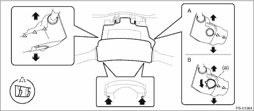
A | Model without keyless access with push button start | B | Model with keyless access with push button start |
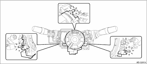
6. Remove the steering roll connector.
CAUTION:
Make sure that the steering roll connector is not turned from the original position.
(1) Disconnect the connector under the steering roll connector.
(2) Release the claws and remove the steering roll connector.
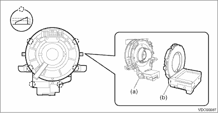
7. Remove the steering angle sensor.
(1) Release the claws and remove the steering angle sensor (b) from the steering roll connector (a).
8. Install the steering angle sensor.
(1) Apply grease to the protrusion (a) of the new steering angle sensor.
CAUTION:
Do not rotate the steering angle sensor protrusion.
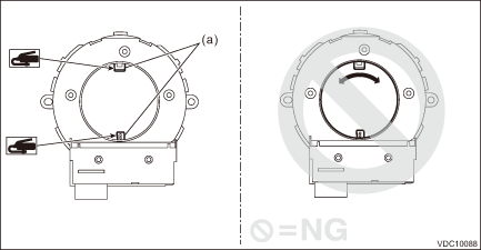
(2) Align the center of steering roll connector. Roll Connector > INSTALLATION">
(3) Align the position of the protrusion and install the steering angle sensor to the steering roll connector.
9. Install each part in the reverse order of removal.
Tightening torque:
Steering wheel: 39 N·m (4.0 kgf-m, 28.8 ft-lb)
Clearance:
Between cover assembly - column and steering wheel: 4 — 6 mm (0.16 — 0.24 in)
10. Adjust the steering angle sensor. (Models without EyeSight) VDC Control Module and Hydraulic Control Unit (VDCCM&H/U) > ADJUSTMENT">
11. Adjust the steering angle sensor. (Models with EyeSight)
• Neutral of Steering Angle Sensor & Lateral G Sensor 0 point setting VDC Control Module and Hydraulic Control Unit (VDCCM&H/U) > ADJUSTMENT">
• Longitudinal G sensor & lateral G sensor 0 point setting VDC Control Module and Hydraulic Control Unit (VDCCM&H/U) > ADJUSTMENT">
 Note
Note
VEHICLE DYNAMICS CONTROL (VDC) > Yaw Rate and G SensorNOTEYaw rate & longitudinal G and lateral G sensor are integrated with the VDC control module & hydraulic control module (VDCCM&H/U ...

Other materials:
Dtc c1311 fr hold valve
VEHICLE DYNAMICS CONTROL (VDC) (DIAGNOSTICS) > Diagnostic Procedure with Diagnostic Trouble Code (DTC)DTC C1311 FR HOLD VALVENOTE:For the diagnostic procedure, refer to “DTC C1362 NORMAL CLOSING VALVE 2”. Diagnostic Procedure with Diagnostic Trouble Code (DTC) > DTC C1362 NORMAL C ...
Removal
FUEL INJECTION (FUEL SYSTEMS)(H4DO) > Throttle BodyREMOVAL1. Disconnect the ground cable from battery.2. Lift up the vehicle.3. Remove the under cover. Front Under Cover > REMOVAL">4. Drain approximately 3.0 L (3.2 US qt, 2.6 Imp qt) of coolant. Engine Coolant > REPLACEMENT"& ...
Installation
DRIVE SHAFT SYSTEM > Propeller ShaftINSTALLATION1. Before installation, check the following items, and replace the propeller shaft assembly as necessary.• Dents or cracks on the tube surface• Splines for deformation or abnormal wear• Unsmooth joint operation or abnormal noise&bu ...
