Subaru Crosstrek Service Manual: Removal
AIRBAG SYSTEM > Passenger’s Airbag Module
REMOVAL
CAUTION:
Before handling the airbag system components, refer to “CAUTION” of “General Description” in “AIRBAG SYSTEM”. General Description > CAUTION">
1. Turn the ignition switch to OFF.
2. Disconnect the ground cable from battery and wait for at least 60 seconds before starting work. NOTE">
NOTE:
On CVT models, shift the select lever into “N” before disconnecting the battery ground cable.
3. Remove the console box assembly, the cover - shift lever and the panel center LWR on the RH and LH sides. Console Box > REMOVAL">
4. Remove the cover - instrument panel side LH and the cover assembly - instrument panel LWR driver. Instrument Panel Lower Cover > REMOVAL">
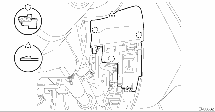
5. Remove the cover switch - starter. (Models without the keyless access with push button start)
(1) Release the claws and remove the cover switch - starter.
(2) Disconnect the connector and aspirator hose.
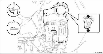
6. Remove the panel - switch. (Model with keyless access with push button start)
(1) Release the claw of the switch - push button start, and disconnect the connector.
(2) Release the claws, and then remove the panel - switch.
(3) Disconnect the connector and aspirator hose.
7. Remove the knee airbag module. Knee Airbag Module > REMOVAL">
8. Release the clips and claws, then detach the left and right grille speaker side.
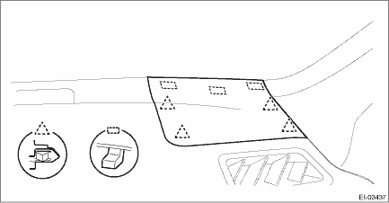
NOTE:
Remove the grille speaker side by using a plastic remover.
9. Remove the trim panel - front pillar UPR on the left and right sides. Upper Inner Trim > REMOVAL">
10. Remove the glove box assembly. Glove Box > REMOVAL">
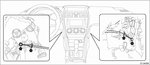
11. On manual A/C models, disconnect the control cables from both sides of the heater & cooling unit.
12. Remove the center grille assembly. Air Vent Grille > REMOVAL">
13. Remove the audio assembly or navigation assembly. Audio > REMOVAL">
14. Remove the multi-function display assembly. Multi-function Display (MFD) > REMOVAL">
15. Remove the combination meter assembly. Combination Meter > REMOVAL">
16. Disconnect the passenger’s airbag module connector. Airbag Connector > PROCEDURE">

17. Remove the column assembly - steering. Steering Column > REMOVAL">
18. Remove the cover side sill - front INN and cover side sill - front on the RH and LH side. Lower Inner Trim > REMOVAL">
19. Remove the body side weather strip - flange front.
20. Remove the instrument panel assembly and the beam COMPL - steering as a unit. Instrument Panel Assembly > REMOVAL">
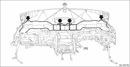
21. Remove the screws and remove the front (A) and side vent duct LH/RH (B).
22. Separate the panel COMPL - instrument and the beam COMPL - steering.
(1) Remove the clamps and bolts of the passenger’s airbag module harness.
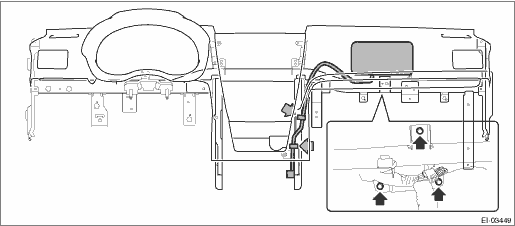
(2) Remove the left and right speakers and the sunload sensor.
NOTE:
Detach the harness clamp together.
(3) Disconnect the front accessory socket connector.
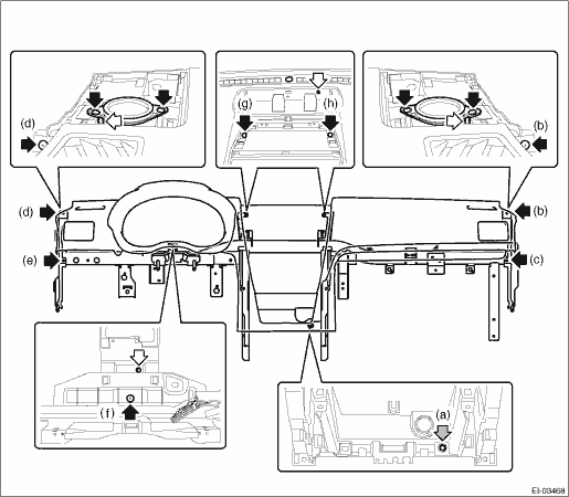
(4) Remove the nut (a) and screws (b), (c), (d), (e), (f), (g) and (h).
(5) While being careful with the harness, separate the panel COMPL - instrument and the beam COMPL - steering.
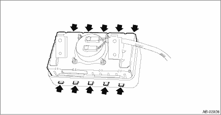
23. Remove the claws, and remove the passenger’s airbag module.
24. For handling of the removed airbag module, refer to “CAUTION”. General Description > CAUTION">
 Installation
AIRBAG SYSTEM > Passenger’s Airbag ModuleINSTALLATIONCAUTION:• Before handling the airbag system components, refer to “CAUTION” of “General Description” in &ldqu ...
 Roll connector
...
Other materials:
Windows
WARNING
To avoid serious personal injury
caused by entrapment, always conform
to the following instructions
without exception.
When operating the power windows,
be extremely careful to
prevent anyone's fingers, arms,
neck, head or other objects from
being caught in the window.
Alwa ...
Inspection
FUEL INJECTION (FUEL SYSTEMS)(H4DO) > Crankshaft Position SensorINSPECTION1. CRANKSHAFT POSITION SENSOR (METHOD WITH OSCILLOSCOPE)1. Prepare an oscilloscope.2. Remove the glove box. Glove Box > REMOVAL">3. Connect the probe to ECM connector.Terminal No.Probe16+1−4. Start the eng ...
Adjustment
DIFFERENTIALS > Rear Differential (VA-type)ADJUSTMENT1. SIDE GEAR BACKLASHAdjust the side gear backlash. Rear Differential (VA-type) > ASSEMBLY">2. HYPOID DRIVEN GEAR BACKLASHAdjust hypoid driven gear backlash. Rear Differential (VA-type) > ASSEMBLY">3. TOOTH CONTACT BETWE ...
