Subaru Crosstrek Service Manual: Removal
REAR SUSPENSION > Rear Sub Frame
REMOVAL
1. Disconnect the ground cable from battery. NOTE">
2. Lift up the vehicle, and then remove the rear wheels.
3. Remove the bolts and clips, and remove the under cover - front.
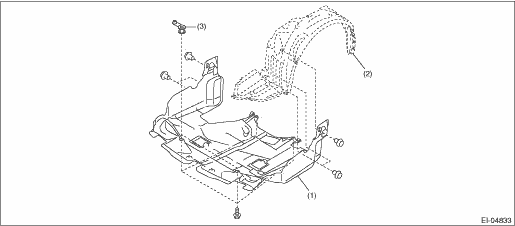
(1) | Under cover - front | (2) | Mud guard - front | (3) | Spacer - under cover |
4. Remove the exhaust pipe and muffler.
• Center exhaust pipe & rear exhaust pipe: Rear Exhaust Pipe > REMOVAL">
• Muffler: Muffler > REMOVAL">
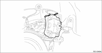
5. Remove the bolts to remove the front heat shield cover.
6. Remove the propeller shaft assembly. Propeller Shaft > REMOVAL">
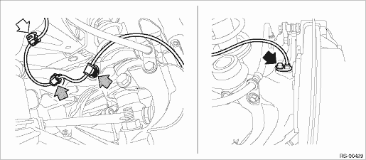
7. Remove the rear ABS wheel speed sensor from the housing assembly - rear axle.
(1) Remove the bolts, and remove the rear ABS wheel speed sensor.
(2) Remove the rear ABS wheel speed sensor harness from the upper arm assembly.
CAUTION:
• Be careful not to damage the sensor.
• Do not apply excessive force to the sensor harness.
• Leave the sensor harness clamp (white arrow) on the vehicle side.
8. Remove the caliper body assembly from the housing assembly - rear axle.
(1) Remove the bolts and then remove the brake hose bracket and caliper body assembly.
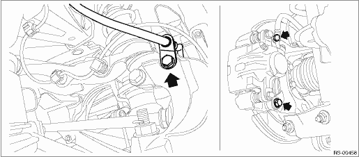
(2) Prepare wiring harnesses etc. to be discarded, and suspend the caliper body assembly from the shock absorber assembly with the harnesses.
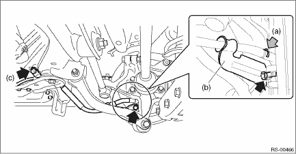
9. Remove the rear parking brake cable from the parking brake assembly. Parking Brake Assembly (Rear Disc Brake) > REMOVAL">
10. Remove the rear parking brake cable from the back plate - rear brake.
(1) Remove the clamp B - hand brake cable (a) from the back plate - rear brake.
(2) Remove the cable clamp (b) from the back plate - rear brake.
(3) Remove the cable clamp (c) and pull out the cable assembly - parking brake.
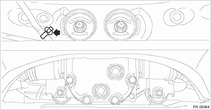
11. Remove the clamp of the sub rear harness.
12. Remove the sensor assembly - headlight beam leveler. (Model with auto headlight beam leveler, left side only)
CAUTION:
Do not apply impact to the sensor assembly - headlight beam leveler or forcibly move the arm. Doing so may cause sensor damage and malfunction.
(1) Disconnect the connector of the sensor assembly - headlight beam leveler.
(2) Remove the nuts, and remove the sensor assembly - headlight beam leveler.
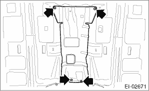
13. Remove the bolt and nuts and remove the fuel tank protector. Fuel Tank Protector > REMOVAL">
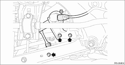
14. Remove the rear sub frame assembly.
(1) Remove the bolts, and remove the stay - rear frame COMPL.
(2) Remove the bolts from the lower side of rear shock absorber assembly.
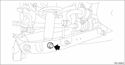
(3) Support the rear sub frame assembly using a transmission jack.
(4) Remove the bolt, and remove the left and right sub frame supports.
(5) Remove the bolts, then remove the rear sub frame assembly.
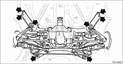
15. As necessary, remove each part from the rear sub frame assembly.
 Inspection
REAR SUSPENSION > Rear Sub FrameINSPECTIONCheck the removed parts for wear, damage and crack, and repair or replace them if faulty. ...
 Installation
REAR SUSPENSION > Rear Sub FrameINSTALLATIONCAUTION:• Be sure to use a new self-locking nut.• Always tighten the bushing in the state where the vehicle is at curb weight and the wheels ...
Other materials:
Removal
FUEL INJECTION (FUEL SYSTEMS)(H4DO) > Engine Wiring HarnessREMOVAL1. Release the fuel pressure. Fuel > PROCEDURE">2. Disconnect the ground cable from battery.3. Remove the intake manifold. Intake Manifold > REMOVAL">4. Disconnect the connector from the engine.• Struc ...
Inspection
SEATS > Front SeatINSPECTION1. SEAT COVERCheck that there is no tear or fray on the cover COMPL - front backrest and the cover - front cushion.NOTE:For model with side airbag, if the door side of the cover COMPL - front backrest is torn or frayed, the side airbag may not be deployed properly. In ...
Memory function
The Subaru Ascent power rear gate is equipped with a convenient memory function
that allows you to store a preferred opening height for everyday use. This feature
is especially useful in garages or areas with limited vertical clearance.
Registration of the rear gate height
To set and save your ...
