Subaru Crosstrek Service Manual: Installation
REAR SUSPENSION > Rear Sub Frame
INSTALLATION
CAUTION:
• Be sure to use a new self-locking nut.
• Always tighten the bushing in the state where the vehicle is at curb weight and the wheels are in full contact with the ground.
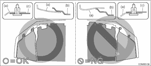
• Install so that the front end of the under cover (b) comes inside the bumper face - front (a), and the front end of the mud guard (c) comes outside the bumper face - front (a).
1. Check the removed parts for wear, damage and crack, and repair or replace them if faulty.
2. Install each part in the reverse order of removal.
Tightening torque:
• Rear suspension parts: General Description > COMPONENT">
• Fuel tank protector: Fuel Tank Protector > REMOVAL">
• Rear disc brake parts: General Description > COMPONENT">
• Parking brake parts: General Description > COMPONENT">
• Exhaust pipe parts: General Description > COMPONENT">
• Propeller shaft parts: Propeller Shaft > INSTALLATION">
3. Install the under cover - front.
Tightening torque:
18 N·m (1.84 kgf-m, 13.3 ft-lb)
4. Bleed air from brake system. Air Bleeding > PROCEDURE">
5. Install the rear wheels.
Tightening torque:
Except for C4 model: 120 N·m (12.24 kgf-m, 88.5 ft-lb)
C4 model: 100 N·m (10.20 kgf-m, 73.8 ft-lb)
6. Inspect the wheel alignment and adjust if necessary.
• Inspection: Wheel Alignment > INSPECTION">
• Adjustment: Wheel Alignment > ADJUSTMENT">
CAUTION:
When the wheel alignment has been adjusted, perform the following VDC setting mode.
– Model without EyeSight: VDC sensor midpoint setting mode VDC Control Module and Hydraulic Control Unit (VDCCM&H/U) > ADJUSTMENT">
– Model with EyeSight: Neutral of Steering Angle Sensor & Lateral G Sensor 0 point setting VDC Control Module and Hydraulic Control Unit (VDCCM&H/U) > ADJUSTMENT">
– Model with EyeSight: Longitudinal G sensor & lateral G sensor 0 point setting VDC Control Module and Hydraulic Control Unit (VDCCM&H/U) > ADJUSTMENT">
7. Connect the battery ground terminal.
8. Perform reinitialization of the auto headlight beam leveler system. (Model with auto headlight beam leveler) Auto Headlight Beam Leveler System > PROCEDURE">
 Removal
REAR SUSPENSION > Rear Sub FrameREMOVAL1. Disconnect the ground cable from battery. NOTE">2. Lift up the vehicle, and then remove the rear wheels.3. Remove the bolts and clips, and remove ...

Other materials:
Installation
WHEEL AND TIRE SYSTEM > Tire Pressure Monitoring SystemINSTALLATION1. TRANSMITTER (TIRE INFLATION PRESSURE SENSOR)CAUTION:Use the new transmitter assembly or replace the new valve and screw, when installing.1. Replace the valve and screw with a new part when reusing transmitter.(1)Screw(2)Transmi ...
Locking and unlocking
Release button
Mechanical key
While pressing the release button of the
access key, take out the mechanical key.
Lock or unlock the driver's door with the
mechanical key in the procedure described
in "Locking and unlocking from
the outside" F2-5.
NOTE
After locking or unlocking, ...
PIN Code Access (models with "keyless access with push-button start system")
Rear lock button
While all doors (including the rear gate)
are locked, you can unlock the doors
(including the rear gate) without a key by
pressing the rear lock button.
NOTE
PIN Code Access will be helpful if the
key is accidentally left in the vehicle. It
is recommended that a 5-d ...
