Subaru Crosstrek Service Manual: Removal
GLASS/WINDOWS/MIRRORS > Windshield Glass
REMOVAL
1. USING WINDSHIELD GLASS KNIFE
CAUTION:
• For model with EyeSight, always remove the glass - front window after the stereo camera is removed.
• For model with EyeSight, always use Subaru genuine windshield glass specially designed for EyeSight. (If the windshield glass other than the glass specially designed for EyeSight is used, the visibility of the camera is blocked or the distortion of the glass prevents the correct measurement of the object, resulting in the EyeSight abnormal operation.)
• For model with EyeSight, if the windshield glass is installed after removal or replaced, always perform the “Inspection” and “Adjustment and check” of the stereo camera.
Inspection: General Description > INSPECTION">
Adjustment and check: Camera Adjustment, Inspection">
• For model with EyeSight, if the damage is found in the glass repair prohibited area, always replace the glass. Damage in the prohibited area can affect the recognition of the stereo camera even if it is repaired, and thereby EyeSight function may not operate properly.
1. Disconnect the ground cable from battery. (Models with wiper deicer) NOTE">
2. Remove the trim panel - front pillar UPR. Upper Inner Trim > REMOVAL">
3. Remove the cowl panel assembly. Cowl Panel > REMOVAL">
4. Disconnect the wiper deicer connector. (Models with wiper deicer)
5. Remove the stereo camera cover and stereo camera. (Models with EyeSight) Stereo Camera > REMOVAL">
6. Remove the molding - front window from the glass - front window, and attach protective tape on the body side of the circumference of the glass - front window.
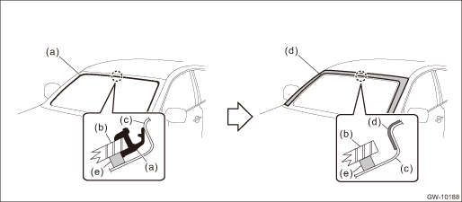
(a) | Molding - front window | (c) | Body panel | (e) | Adhesive |
(b) | Glass - front window | (d) | Protective tape |
7. Remove the glass - front window.
(1) Apply sufficient amount of soapy water to the adhesive part and insert the windshield glass knife.
(2) While holding the edges of the knife and the glass - front window at a right angle, move the windshield glass knife parallel to the edge of the glass - front window, and cut the adhesive along the surface and the edge of the glass - front window.
CAUTION:
• Cutting of adhesive part should be started from an area with wider gap between the glass - front window and the body.
• Never twist the windshield glass knife.
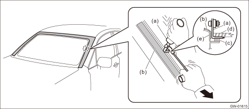
(a) | Windshield glass knife | (c) | Adhesive | (e) | Body panel |
(b) | Protective tape | (d) | Glass - front window |
(3) Disconnect the locating pin - front window, and remove the glass - front window.
NOTE:
The locating pin - front window are bonded to the corners of the glass - front window. Use piano wire to disconnect the pins.
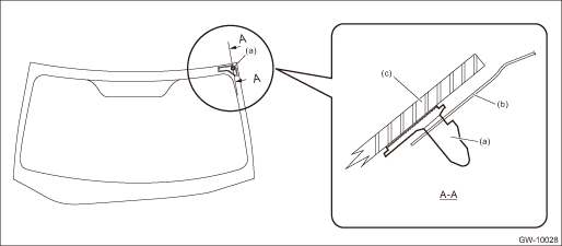
(a) | Locating pin - front window | (b) | Body panel | (c) | Glass - front window |
2. USING PIANO WIRE
CAUTION:
• Do not tightly pull the piano wire against the glass - front window edge.
• Apply protective tape, etc, and be careful that the inner and outer components of the vehicle are not damaged.
• Do not cross piano wires. Otherwise they may be cut.
1. Disconnect the ground cable from battery. (Models with wiper deicer) NOTE">
2. Remove the trim panel - front pillar UPR. Upper Inner Trim > REMOVAL">
3. Remove the cowl panel assembly. Cowl Panel > REMOVAL">
4. Disconnect the wiper deicer connector. (Models with wiper deicer)
5. Remove the stereo camera cover and stereo camera. (Models with EyeSight) Stereo Camera > REMOVAL">
6. Remove the molding - front window from the glass - front window, and attach protective tape on the body side of the circumference of the glass - front window.
(a) | Molding - front window | (c) | Body panel | (e) | Adhesive |
(b) | Glass - front window | (d) | Protective tape |
7. Remove the glass - front window.
(1) Using a drill, make a hole in the adhesive part.
(2) Pass the piano wire through the hole, and pull the wire ends alternately to cut off the adhesive part and the locating pin - front window.
CAUTION:
Attach a piece of wood to both piano wire ends.
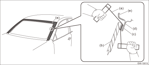
(a) | Piano wire | (c) | Adhesive | (e) | Protective tape |
(b) | Glass - front window | (d) | Body panel |
 Installation
GLASS/WINDOWS/MIRRORS > Windshield GlassINSTALLATIONCAUTION:• For model with EyeSight, always use Subaru genuine windshield glass specially designed for EyeSight. (If the windshield glass oth ...

Other materials:
Dtc u0416 invalid data received from vehicle dynamics control module
HVAC SYSTEM (AUTO A/C) (DIAGNOSTICS) > Diagnostic Procedure with Diagnostic Trouble Code (DTC)DTC U0416 INVALID DATA RECEIVED FROM VEHICLE DYNAMICS CONTROL MODULEThis is detected when CAN data from VDC is abnormal.NOTE:Perform the diagnosis for LAN system. Basic Diagnostic Procedure > PROCEDU ...
Open/close
To open:
First unlock the rear gate lock then push
the rear gate opener button.
To close:
Lower the rear gate slowly and push down firmly until the latch engages.
The rear gate can be lowered easily if you
pull it down holding the recessed grip.
WARNING
To prevent dangerous exhaust
...
Operation
INSTRUMENTATION/DRIVER INFO > Multi-function Display (MFD) SystemOPERATION1. DIAGNOSTIC MODE (HIGH GRADE TYPE ONLY)The settings of the multi-function display can be changed by performing the following procedures to display the diagnostic mode. To show the demonstration display only, refer to &ldq ...
