Subaru Crosstrek Service Manual: Removal
EXTERIOR/INTERIOR TRIM > Rear Bumper
REMOVAL
1. CROSSTREK MODEL
1. Disconnect the ground cable from battery. NOTE">
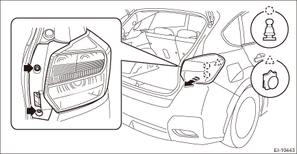
2. Remove the light assembly - rear combination.
CAUTION:
Be careful not to damage the clips.
(1) Release the bolts and clips, then pull out the light assembly - rear combination to the vehicle rear.
(2) Disconnect the connector and remove the light assembly - rear combination.
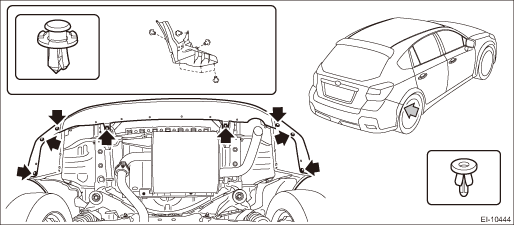
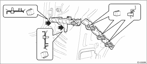
3. Remove the bumper face - rear.
(1) Remove the clips inside the wheel housing.
(2) Remove the clips at the lower side of the bumper face - rear.
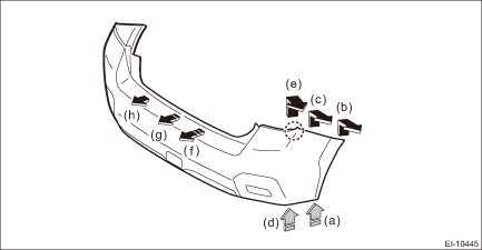
(3) Detach (b) and (c) while pulling up (a) of the bumper face - rear.
(4) Detach (e) while pulling up (d) of the bumper face - rear.
(5) Detach the opposite side in the same manner.
(6) Detach in order from (f) to (h) while pulling up the center part of the bumper face - rear.
CAUTION:
Do not pull forcibly. It may damage the flange section on the bumper face - rear side when it comes off from the claws of the bracket - rear bumper.
4. Remove the bolts and nuts, and remove the bumper beam COMPL - rear.
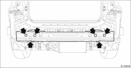
NOTE:
After all nuts are removed, raise the bumper beam COMPL - rear a little to remove it from vehicle body.
5. Remove bumper brackets.
(1) Remove the screws.
(2) Turn over the trim panel - rear apron, and detach the claw of the clip from the back side.
(3) Remove the clip, and remove the bracket - rear bumper lower.
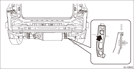
6. From behind the bumper, release the claws, and remove the reflex reflector assembly.
 Repair
EXTERIOR/INTERIOR TRIM > Rear BumperREPAIRRefer to the description concerning repair in “Front Bumper” section. Front Bumper > REPAIR"> ...

Other materials:
List
INSTRUMENTATION/DRIVER INFO (DIAGNOSTICS) > System Operation Check ModeLIST• Combination meter (models with normal meters)Check itemItem 1Item 2NoteMeter Needle Movement CheckSpeedometerSpeedometer 0 km/h (MPH) indication — Speedometer 40 km/h (MPH) indication — Speedometer 80 km/h (MPH ...
Radiator cap Inspection
COOLING(H4DO) > Radiator CapINSPECTION1. Check that the radiator cap does not have deformation, cracks or damage.2. Attach the radiator cap tester to radiator cap.3. Increase pressure until the radiator cap tester gauge needle stops. Radiator cap is functioning properly if it holds the service li ...
Towing
If towing is necessary, it is best done by
your SUBARU dealer or a commercial
towing service. Observe the following
procedures for safety.
WARNING
Never tow AWD models with the
front wheels raised off the ground
while the rear wheels are on the
ground, or with the rear wheels
raised off t ...
