Subaru Crosstrek Service Manual: Operation
ENTERTAINMENT > Audio System
OPERATION
1. SUBARU STARLINK CONNECTION ID DISPLAY
Model with 6.2 inch display
1. Turn the ignition switch to ACC.
2. Press the HOME button (a) to display the {HOME} screen.
3. Touch the {SETTINGS} (b) to display the {SETTINGS} screen.
4. Touch the {Settings General} (c) to display the {Settings General} screen.
5. Touch the {Version} (d) in {System Software}.
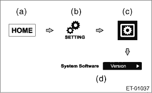
6. Confirm the Serial Number (8 digits).
Model with 7 inch display
Operation is the same as that of navigation assembly, therefore, refer to “Navigation System”. Navigation System > OPERATION">
2. SOFTWARE VERSION DISPLAY
Model with 6.2 inch display
1. Perform the same procedure as for the SUBARU STARLINK connection ID display. Audio System > OPERATION">
2. Confirm the Software Ver.
Model with 7 inch display
Operation is the same as that of navigation assembly, therefore, refer to “Navigation System”. Navigation System > OPERATION">
3. INITIALIZATION (FACTORY DEFAULT)
Model with 6.2 inch display
1. Turn the ignition switch to ACC.
2. Press the HOME button (a) to display the {HOME} screen.
3. Touch the {SETTINGS} (b) to display the {SETTINGS} screen.
4. Touch the {Settings General} (c) to display the {Settings General} screen.
5. Touch the {Restore} (d) in {Reset to Factory Settings}.

6. Touch {OK} after {Are you sure you want to delete All Data?} is displayed.
7. {DO NOT OPERATE. Initializing now.} is displayed, and all data deletion is initiated.
8. When all data is deleted, {All date has been deleted. Start up the engine to reboot.} is displayed.
Model with 7 inch display
Operation is the same as that of navigation assembly, therefore, refer to “Navigation System”. Navigation System > OPERATION">
4. CHECK CONNECTIONS WITH LINE DIAG MODE
Model with 6.2 inch display
1. Turn the ignition switch to ACC.
2. Press the button (a) to display the Audio OFF screen.
3. Touch the screen in order from (b) to (e).

NOTE:
Pressing the button (a) or turning the ignition switch from the OFF to ACC position can exit the Line Diag mode.
4. {Line Diag} screen is displayed.
5. Check the connection status with the {Connectivity Check} in the {Line Diag} screen.

OK: Each connection device is connected properly.
NG: No connection or abnormal connection is detected.
NOTE:
Check the external connection terminals (USB 1, 2 and AUX) by connecting a memory for check or a pin jack.
Model with 7 inch display
Operation is the same as that of navigation assembly, therefore, refer to “Navigation System”. Navigation System > OPERATION">
5. CHECK VEHICLE SIGNALS WITH LINE DIAG MODE
Model with 6.2 inch display
1. Turn the ignition switch to ACC.
2. Press the button (a) to display the Audio OFF screen.
3. Touch the screen in order from (b) to (e).
NOTE:
Pressing the button (a) or turning the ignition switch from the OFF to ACC position can exit the diagnostic mode.
4. {Line Diag} screen is displayed.
5. Check the connection status with the {Vehicle Signal Check} in the {Line Diag} screen.
• Check illumination
NOTE:
Make sure that the bright switch is not ON.
1. Set the lighting switch to the parking position.
2. Make sure that {OK} lights in ILL+ and then the screen becomes dim.
OK: Normal.
NG: Abnormal. Check the signal line connector. If there are no problems, the unit could be faulty.
• Check speed sensor
NOTE:
– Before starting inspections, check the safety around the vehicle.
– Lift up the vehicle as necessary.
– When the diagnostic trouble code is input in the VDC CM, perform the Clear Memory Mode.
1. Drive the vehicle at 8 km/h (5 MPH) or more.
2. Check that {OK} is displayed in SPD.
OK: Normal.
NG: Vehicle speed is less than 8 km/h (5 MPH), or malfunction is detected in the signal line. Check the signal line connector. If there are no problems, the unit could be faulty.
• Check parking brake signal
1. Pull parking brake lever.
2. Check that {OK} is displayed in PKB.
OK: Normal.
NG: Abnormal. Check the signal line connector. If there are no problems, the unit could be faulty.
• Check back sensor
NOTE:
Before starting inspections, check the safety behind the vehicle.
1. Turn the ignition to ON.
2. Pull the parking brake lever and depress the brake pedal, then place the select lever or gear shift lever in reverse.
3. Make sure that {OK} is displayed in REV.
OK: Normal.
NG: Abnormal. Check the signal line connector. If there are no problems, the unit could be faulty.
Model with 7 inch display
Operation is the same as that of navigation assembly, therefore, refer to “Navigation System”. Navigation System > OPERATION">
6. CHECK SPEAKER OUTPUT WITH LINE DIAG MODE
Model with 6.2 inch display
1. Turn the ignition switch to ACC.
2. Press the button (a) to display the Audio OFF screen.
3. Touch the screen in order from (b) to (e).
NOTE:
Pressing the button (a) or turning the ignition switch from the OFF to ACC position can exit the Line Diag mode.
4. {Line Diag} screen is displayed.
5. Touch {Audio Check} on the {Line Diag} screen.
6. {Audio Check} screen is displayed.

7. Touch the {ON} key of {Speaker Check} to check speaker output.
NOTE:
• The speaker front left > front right > rear right > rear left will sound in order for 2 seconds each.
• The speaker sounds at the maximum volume during speaker check.
• Press the {BACK} key to return to the {Line Diag} screen.
Model with 7 inch display
Operation is the same as that of navigation assembly, therefore, refer to “Navigation System”. Navigation System > OPERATION">
7. CHECK RADIO FREQUENCY RANGE SWITCH-OVER
NOTE:
• Displayed only for model with 6.2 inch display.
• Some items are not displayed according to destination.
1. Turn the ignition switch to ACC.
2. Press the button (a) to display the Audio OFF screen.
3. Touch the screen in order from (b) to (e).
NOTE:
Pressing the button (a) or turning the ignition switch from the OFF to ACC position can exit the Line Diag mode.
4. {Line Diag} screen is displayed.
5. Touch {Dealer Diag} on the {Line Diag} screen.
6. The {Dealer Diag} screen is displayed.
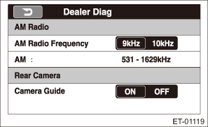
7. Touch the {9kHz} or {10kHz} key to switch the AM radio frequency range.
Display key | Frequency range | ||||
9 kHz | Set the AM frequency range to 531 — 1629 kHz. | ||||
10 kHz | Set the AM frequency range to 530 — 1710 kHz. | ||||
NOTE:
• When the setting is changed, reboot confirmation for frequency switch-over is displayed. Select {OK} to reboot. When {cancel} is pressed, the {Dealer Diag} screen is displayed.
• The initial settings is at 9 kHz.
 Note
Note
ENTERTAINMENT > Audio SystemNOTEFor procedure of each component in the audio system, refer to the respective sections.• Audio unit: Audio">• Front speaker– Tweeter (instrume ...

Other materials:
Dtc u0140 lost communication with body control module
CONTINUOUSLY VARIABLE TRANSMISSION (DIAGNOSTICS) > Diagnostic Procedure with Diagnostic Trouble Code (DTC)DTC U0140 LOST COMMUNICATION WITH BODY CONTROL MODULENOTE:Refer to “LAN SYSTEM (DIAGNOSTICS)” for diagnostic procedures. Basic Diagnostic Procedure">1. OUTLINE OF DIAGNOS ...
Wiring diagram
SECURITY AND LOCKS > Door Lock Control SystemWIRING DIAGRAMFor wiring diagrams related to the door lock control system, refer to the following items.• Keyless entry system: Keyless Entry System > WIRING DIAGRAM">• Keyless access system: Keyless Access System > WIRING D ...
Dtc b14ea intake door actuator circuit short-circuit
HVAC SYSTEM (AUTO A/C) (DIAGNOSTICS) > Diagnostic Procedure with Diagnostic Trouble Code (DTC)DTC B14EA INTAKE DOOR ACTUATOR CIRCUIT SHORT-CIRCUITDTC detecting condition:Intake door actuator potentiometer circuit is shorted.Trouble symptom:FRESH/RECIRC does not operate.Wiring diagram:Air conditio ...
