Subaru Crosstrek Service Manual: Installation
WHEEL AND TIRE SYSTEM > Tire Pressure Monitoring System
INSTALLATION
1. TRANSMITTER (TIRE INFLATION PRESSURE SENSOR)
CAUTION:
Use the new transmitter assembly or replace the new valve and screw, when installing.
1. Replace the valve and screw with a new part when reusing transmitter.
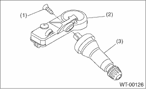
(1) | Screw |
(2) | Transmitter |
(3) | Valve |
Tightening torque:
1.4 N·m (0.14 kgf-m, 1.0 ft-lb)
2. Install the transmitter to the wheel by aligning it with valve hole.
NOTE:
When using the jig that pulls the valve cap by hooking its neck part, use another short-type cap.
3. Install the tires to wheels.
CAUTION:
• Use a tire changer when installing tire to wheel.
• To prevent damaging the transmitter, set the tire changer boom in the position as shown in the figure.
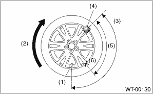
(1) | Transmitter |
(2) | Direction of turn table rotation |
(3) | 135° |
(4) | Tire changer boom |
(5) | 90° |
(6) | Starting point for fitting the bead to the rim |
4. Install the wheels to vehicle. Tire and Wheel > INSTALLATION">
5. Register the transmitter ID to the TPMS & keyless control module. Register Transmitter (ID)">
2. TPMS & KEYLESS CONTROL MODULE
Install each part in the reverse order of removal.
Tightening torque:
13 N·m (1.33 kgf-m, 9.6 ft-lb)
3. TPMS CM
Install each part in the reverse order of removal.
Tightening torque:
7.5 N·m (0.76 kgf-m, 5.5 ft-lb)
 Removal
WHEEL AND TIRE SYSTEM > Tire Pressure Monitoring SystemREMOVAL1. TRANSMITTER (TIRE INFLATION PRESSURE SENSOR)1. Remove the wheels from the vehicle. Tire and Wheel > REMOVAL">2. Remove t ...
 General diagnostic table Inspection
WHEEL AND TIRE SYSTEM > General Diagnostic TableINSPECTIONSymptomsPossible causeCorrective actionWheel is out of balance.Improperly inflated tire.Adjust the tire pressure.Uneven wearCheck the tire ...
Other materials:
Removal
SECURITY AND LOCKS > Access BuzzerREMOVAL1. Disconnect the ground cable from battery. NOTE">2. Lift up the vehicle.3. Remove the clips and screws, and turn over the front side of the mud guard - front RH.4. Remove the access buzzer.(1) Disconnect the connector.(2) Remove the clip and det ...
Installation
CONTROL SYSTEMS > Select CableINSTALLATION1. Position the select cable as shown in the figure, and install it to the plate assembly.CAUTION:• If the cable is installed in the wrong direction, loosen the bracket bolts, and then reinstall the cable in the correct direction.• Do not adju ...
Inspection
LIGHTING SYSTEM > Turn Signal Light & Hazard Light UnitINSPECTION1. Disconnect the connector of the turn signal & hazard unit.2. Measure the voltage between the turn signal & hazard unit connector and the chassis ground.Preparation tool:Circuit testerTerminal No.Inspection conditionsS ...
