Subaru Crosstrek Service Manual: Installation
POWER ASSISTED SYSTEM (POWER STEERING) > Universal Joint
INSTALLATION
1. Before installation, check the universal joint assembly - steering. Universal Joint > INSPECTION">
2. Adjust the tilt position of the column assembly - steering to the neutral position and lock the tilt lever.
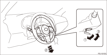
3. Align the cutout portion (a) at serrated section of the column shaft (c) and yoke (b), then install the universal joint assembly - steering into column shaft.
CAUTION:
Be sure to align the protrusion section (a) of the column shaft side with the cutout (a) of the serration. If another cutout portions (d) are used for alignment, the bolt of the universal joint assembly - steering cannot be assembled.
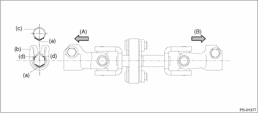
(A) | Column shaft side | (B) | Gearbox side |
4. Install the universal joint assembly - steering to the serrations of the gearbox assembly by matching the alignment marks.
5. Tighten the bolts on the gearbox side first, and then the column shaft side.
CAUTION:
Be sure to follow the tightening order and tightening torque of the universal joint assembly - steering to avoid the steering effort from becoming heavy.
Tightening torque:
24 N·m (2.45 kgf-m, 17.7 ft-lb)
Clearance:
Universal joint assembly - steering coupling to adjacent parts: 15 mm (0.59 in) or more
 Removal
POWER ASSISTED SYSTEM (POWER STEERING) > Universal JointREMOVAL1. Adjust the tilt position of the column assembly - steering to the lowest position and lock the tilt lever.2. Remove the universal j ...
 General diagnostic table Inspection
POWER ASSISTED SYSTEM (POWER STEERING) > General Diagnostic TableINSPECTIONTroublePossible causeCorrective action• Steering effort is heavy in all ranges.• Steering effort is heavy at s ...
Other materials:
Removal
ENTERTAINMENT > External Connection TerminalREMOVAL1. Disconnect the ground cable from battery and wait for at least 60 seconds before starting work. NOTE">2. Remove the console box assembly. Console Box > REMOVAL">3. While pressing the claw, press it in from the rear to remo ...
Inspection
STARTING/CHARGING SYSTEMS(H4DO) > BatteryINSPECTIONWARNING:• As batteries produce flammable gases, be careful not to bring an open flame close to the batteries.• Ventilate sufficiently when using or charging battery in enclosed space.• Electrolyte is corrosive acid, and has toxi ...
Safety precautions
CAUTION
Do not let dust, oil or water get on
or in the access key/transmitter
when replacing battery.
Be careful not to touch or damage
the printed circuit board in
the access key/transmitter when
replacing the battery.
Be careful not to allow children to
touch the battery and an ...
