Subaru Crosstrek Service Manual: Installation
CONTINUOUSLY VARIABLE TRANSMISSION(TR580) > Control Valve Body
INSTALLATION
1. Clean the mating surface of valve cover and transmission side.
CAUTION:
When cleaning the mating surface of the transmission side, be careful not to allow any dust, foreign matter and used liquid gasket to enter the transmission.
2. Check the control valve body for dust and other foreign matter.
3. Install the O-rings.
NOTE:
• Use new O-rings.
• Apply CVTF to the O-rings.
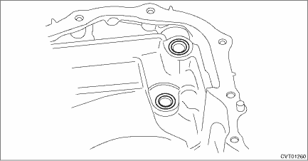
4. Install the control valve body.
(1) Install the control valve body to the transmission.
CAUTION:
• Do not damage the O-ring.
• Perform installation so that the O-ring is not displaced.
(2) Temporarily tighten the bolt (A: silver).
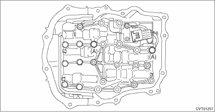
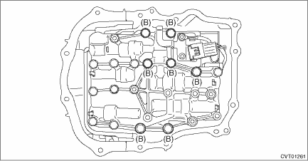
(3) Attach the bolt (B).
Tightening torque:
9 N·m (0.9 kgf-m, 6.6 ft-lb)
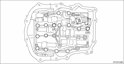
(4) Tighten the bolt (A: silver).
Tightening torque:
9 N·m (0.9 kgf-m, 6.6 ft-lb)
5. Install the O-ring to the transmission harness.
NOTE:
• Use new O-rings.
• Apply CVTF to the O-rings.
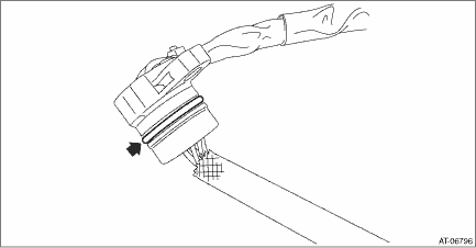
6. Install the transmission harness to the valve cover.
Tightening torque:
7 N·m (0.7 kgf-m, 5.2 ft-lb)
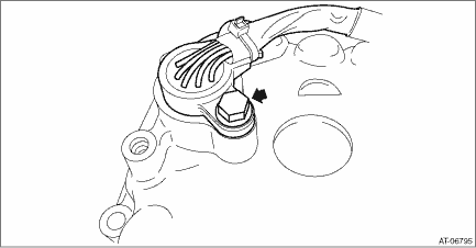
7. Install the gasket to the transmission.
NOTE:
Use a new gasket.
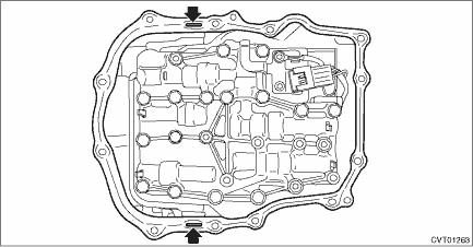
8. Apply liquid gasket to the oval hole of gasket.
Liquid gasket:
THREE BOND 1215B or equivalent
9. Connect the transmission harness connector to the control valve body, and install the valve cover.
CAUTION:
Be careful not to catch the sheet of the ST.
Tightening torque:
8 N·m (0.8 kgf-m, 5.9 ft-lb)
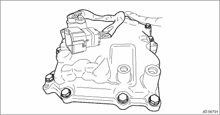
10. Remove the ST (SHEET SPECIAL TOOL).
11. Install the throttle body. Throttle Body > INSTALLATION">
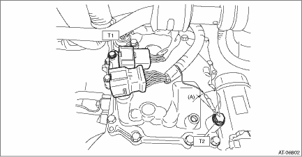
12. Install the transmission harness connector to the harness stay.
13. Install the transmission harness stay and transmission ground terminal.
NOTE:
Install the transmission ground terminal in the direction within the range of approx. 30° (A).
Tightening torque:
T1: 7 N·m (0.7 kgf-m, 5.2 ft-lb)
T2: 14 N·m (1.4 kgf-m, 10.3 ft-lb)
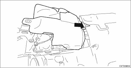
14. Insert the transmission case cover (small) between transmission case cover (large) and transmission to install.
Tightening torque:
8 N·m (0.8 kgf-m, 5.9 ft-lb)
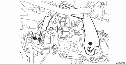
15. Install the pitching stopper bracket and transmission radio ground cord.
CAUTION:
Be careful not to deform or damage the terminal of transmission radio ground cord.
Tightening torque:
41 N·m (4.2 kgf-m, 30.2 ft-lb)
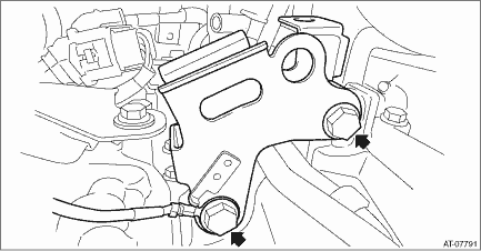
16. Install the air breather hose to the pitching stopper bracket.
17. Install the pitching stopper.
Tightening torque:
T1: 50 N·m (5.1 kgf-m, 36.9 ft-lb)
T2: 58 N·m (5.9 kgf-m, 42.8 ft-lb)
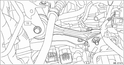
18. Connect the following harness connectors.
• Transmission harness connectors
• Inhibitor harness connector
• Transmission radio ground terminal
Tightening torque:
13 N·m (1.3 kgf-m, 9.6 ft-lb)
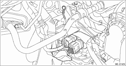
(A) | Transmission harness connectors |
(B) | Inhibitor harness connector |
(C) | Transmission radio ground terminal |
19. Install the air intake boot assembly. Air Intake Boot > INSTALLATION">
20. Adjust the CVTF level. CVTF > ADJUSTMENT">
21. Perform the operation of AT learning mode. Learning Control">
 Removal
CONTINUOUSLY VARIABLE TRANSMISSION(TR580) > Control Valve BodyREMOVALCAUTION:• Directly after the vehicle has been running or the engine has been idling for a long time, the CVTF is hot. Be c ...
 Converter case
...
Other materials:
Connecting a trailer
Ball mount
Hitch pin
Safety pin
Hitch receiver tube
1. Insert the ball mount into the hitch
receiver tube.
2. Insert the hitch pin into the hole
located on the hitch receiver tube so that
the pin passes through the ball mount.
3. Insert the safety pin through the hole
locat ...
Glove box
Lock
Unlock
To open the glove box, pull the handle. To
close it, push the lid firmly upward.
To lock the glove box, insert the key and
turn it clockwise. To unlock the glove box,
insert the key and turn it counterclockwise.
For models with "keyless access with
push-button start s ...
Inspection
VEHICLE DYNAMICS CONTROL (VDC) > VDC OFF SwitchINSPECTION1. Disconnect the VDC OFF switch connector.2. Check the resistance between the VDC OFF switch terminals.PREPARATION TOOL:Circuit testerTerminal No.Inspection conditionsStandard2 — 3Switch OFF1 M? or moreSwitch ONLess than 1 ?3. Replace th ...
