Subaru Crosstrek Service Manual: Inspection
MECHANICAL(H4DO) > Cam Carrier
INSPECTION
1. Visually check the cam carrier filter, and if clogging is found, replace with a new part.
2. Check the camshaft journals for damage and wear. Replace the camshaft if faulty.
3. Check the cam face condition of camshaft, and remove the minor faults by grinding with oil stone. Replace the camshaft if uneven wear is found.
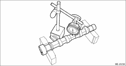
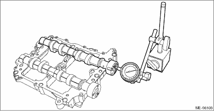
4. Using a dial gauge, check the camshaft bend. If it exceeds the limit, replace the camshaft.
NOTE:
Measurement should be performed at a temperature of 20°C (68°F).
Camshaft bend:
Limit
0.020 mm (0.0008 in)
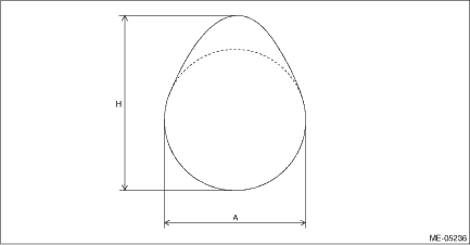
5. Check the cam lobe height “H” and cam base circle diameter “A” of camshaft as shown in the figure, using micrometer. If it is not within the standard, replace the camshaft.
NOTE:
Measurement should be performed at a temperature of 20°C (68°F).
Camshaft cam lobe overall height H:
Intake
Standard
40.34 — 40.44 mm (1.588 — 1.592 in)
Exhaust
Standard
39.66 — 39.76 mm (1.561 — 1.565 in)
Camshaft cam base circle diameter A:
Standard
34.0 mm (1.339 in)
6. Check the camshaft journal outer diameter using micrometer. If it is not within the standard, replace the camshaft.
NOTE:
• Measurement should be performed at a temperature of 20°C (68°F).
• Measure outer diameter of each journal at several points, and read the value of most worn location.
Camshaft journal outer diameter:
Standard
25.946 — 25.963 mm (1.0215 — 1.0222 in)
7. Using a dial gauge, check the thrust clearance of the camshaft. If it is not within the standard or if uneven wear is found, replace each camshaft cap and cam carrier as a set. If necessary replace the camshaft.
NOTE:
• Measurement should be performed at a temperature of 20°C (68°F).
• Set the dial gauge at end surface of camshaft.
Camshaft thrust clearance:
Standard
0.068 — 0.116 mm (0.0027 — 0.0047 in)
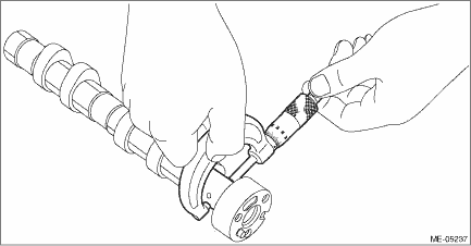
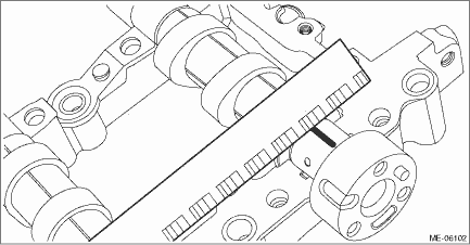
8. Check the oil clearance on the camshaft using a plastigauge.
NOTE:
Measurement should be performed at a temperature of 20°C (68°F).
(1) Remove the liquid gasket from cam carrier and front camshaft cap, intake rear camshaft cap and exhaust rear camshaft cap.
(2) Clean each camshaft cap and cam carrier journals.
(3) Set the camshaft to the cam carrier.
(4) Place a plastigauge across the camshaft journals of each camshaft and set the camshaft caps.
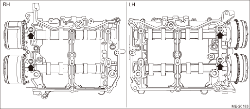
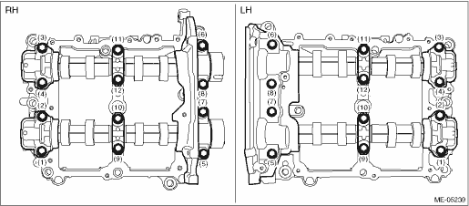
(5) Tighten the bolts which secure front camshaft cap, intake center camshaft cap, intake rear camshaft cap, exhaust center camshaft cap and exhaust rear camshaft cap in numerical order as shown in the figure.
Tightening torque:
18 N·m (1.8 kgf-m, 13.3 ft-lb)

(6) Loosen the bolts (front camshaft cap, intake center camshaft cap, intake rear camshaft cap, exhaust center camshaft cap and exhaust rear camshaft cap) equally, a little at a time in numerical sequence as shown in the figure, and remove each camshaft cap.
(7) Determine camshaft oil clearance by matching the widest point of plastigauge on each journal against scale printed on a package of plastigauge. If it is not within the standard, replace each camshaft cap and cam carrier as a set. If necessary replace the camshaft.
Camshaft oil clearance:
Standard
0.037 — 0.072 mm (0.0015 — 0.0028 in)
(8) Completely remove the plastigauge.
 Disassembly
MECHANICAL(H4DO) > Cam CarrierDISASSEMBLY1. CAM CARRIER RH1. Loosen the bolts (front camshaft cap RH, intake center camshaft cap RH, intake rear camshaft cap RH, exhaust center camshaft cap RH, and ...
 Installation
MECHANICAL(H4DO) > Cam CarrierINSTALLATION1. CAM CARRIER RH1. Insert the steel rods into ST, and set the engine so that the camshaft RH is facing up.CAUTION:• If the engine is standing on one ...
Other materials:
Adjustment
CONTINUOUSLY VARIABLE TRANSMISSION(TR580) > Drive Pinion Shaft AssemblyADJUSTMENT1. Remove the liquid gasket from the mating surface completely.2. Using the ST, install the drive pinion retainer to converter case.ST 18270KA020SOCKET (E20)NOTE:Do not confuse the three different-length bolts whe ...
Tire inspection
Perform a visual inspection of the tires on your Subaru Ascent on a daily basis
to ensure they are free from serious damage, embedded nails, stones, or other foreign
objects. At the same time, carefully examine the tread surface for any signs of
uneven or abnormal wear, which may indicate unde ...
Meters and gauges
NOTE
Some meters and gauges in the Subaru Ascent instrument cluster utilize liquid
crystal displays. If you are wearing polarized sunglasses, visibility of certain
indicators may be reduced.
Speedometer
The Subaru Ascent speedometer provides a clear and precise display of the vehicle’s
cu ...
