Subaru Crosstrek Service Manual: Inspection
HVAC SYSTEM (HEATER, VENTILATOR AND A/C) > Evaporator Sensor
INSPECTION
1. MANUAL A/C MODEL
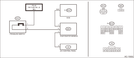
WIRING DIAGRAM:
1. Prepare the vehicle.
NOTE:
Check that the ambient temperature is 25 — 40°C (77 — 104°F) and that the humidity is 30% — 80%.
• Place the vehicle in the workshop or in the shade and windless condition.
• Open all windows.
2. Set the vehicle to the following conditions and idle the engine for 15 minutes.
Item | Condition |
Engine | Idling |
Air vent grille | Shutter is fully open. |
A/C switch | OFF |
Temperature adjustment dial | LO (MAX COOL) |
FRESH/RECIRC switch | RECIRC |
Air flow control dial | VENT |
Fan dial | 3/4 level |
3. Check evaporator sensor power supply input
Preparation tool:
Circuit tester
(1) Turn the ignition switch to OFF.
(2) Disconnect the evaporator sensor connector.
(3) Turn the ignition switch to ON.
(4) Measure the voltage between evaporator sensor connector and chassis ground.
Connector & terminal
(B88) No. 3 (+) — Chassis ground (−):
(5) Is the voltage approx. 12 V?
• Yes > Go to step 4).
• No > Repair or replace the harness.
4. Check evaporator sensor ground circuit
(1) Turn the ignition switch to OFF.
(2) Check continuity between evaporator sensor connector and chassis ground.
Connector & terminal
(B88) No. 2 — Chassis ground:
(3) Is there continuity?
• Yes > Go to step 6).
• No > Go to step 5).
5. Check open circuit in evaporator sensor ground circuit
(1) Disconnect the control panel connector.
(2) Check continuity between evaporator sensor connector and control panel connector.
Connector & terminal
(B88) No. 2 — (i16) No. 2:
(3) Is there continuity?
• Yes > Replace the control panel.
• No > Repair or replace the harness.
6. Check evaporator sensor signal output
(1) Connect the evaporator sensor connector and the control panel connector.
(2) Disconnect the engine control module (ECM) connector.
(3) Turn the ignition switch to ON.
(4) Turn the A/C switch to ON.
(5) Measure the voltage between engine control module (ECM) connector and chassis ground.
Connector & terminal
(B137) No. 26 (+) — Chassis ground (−):
(6) Is the voltage approx. 8 V or more?
• Yes > Evaporator sensor is normal.
• No > Go to step 7).
7. Check open circuit in evaporator sensor signal output circuit
(1) Turn the ignition switch to OFF.
(2) Disconnect the evaporator sensor connector.
(3) Check continuity between evaporator sensor connector and engine control module (ECM) connector.
Connector & terminal
(B88) No. 1 — (B137) No. 26:
(4) Is there continuity?
• Yes > Replace the evaporator sensor.
• No > Repair or replace the harness.
2. AUTO A/C MODEL
1. Prepare the vehicle.
NOTE:
Check that the ambient temperature is 25 — 40°C (77 — 104°F) and that the humidity is 30% — 80%.
• Place the vehicle in the workshop or in the shade and windless condition.
• Open all windows.
2. Set the vehicle to the following conditions.
Item | Condition |
Engine | Idling |
Air vent grille | Shutter is fully open. |
A/C switch | OFF |
Temperature adjustment dial | LO (MAX COOL) |
FRESH/RECIRC switch | RECIRC |
Air flow control dial or switch | VENT |
Fan dial | 5/7 level |
3. Using the Subaru Select Monitor, check «Evaporator Temperature».
NOTE:
For detailed operation procedures, refer to “Application help”.
(1) Idle the engine for 15 minutes, and then compare the air flow outlet temperature with «Evaporator Temperature».
Preparation tool:
Thermometer and hygrometer
NOTE:
For outlet opening temperature, measure the average temperature of center grille assembly and side grille assembly.
(2) Do the air flow outlet temperature and «Evaporator Temperature» differ by 3°C (5.4°F) or more?
• Yes > Go to step 4).
• No > Evaporator sensor is normal.
4. Check the evaporator sensor.
(1) Disconnect the evaporator sensor connector.
(2) Is the resistance between terminals of evaporator sensor within standard value?
Preparation tool:
Circuit tester
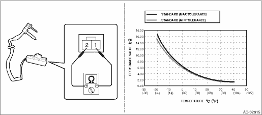
Terminal No. | Inspection conditions | Standard |
1 — 2 | −20°C | 15.37 — 16.62 k? |
−15°C | 12.09 — 12.87 k? | |
−10°C | 9.576 — 10.05 k? | |
−5°C | 7.636 — 7.899 k? | |
0°C | 6.132 — 6.256 k? | |
5°C | 4.891 — 5.057 k? | |
10°C | 3.928 — 4.113 k? | |
15°C | 3.174 — 3.366 k? | |
20°C | 2.581 — 2.77 k? | |
25°C | 2.111 — 2.292 k? | |
30°C | 1.737 — 1.907 k? | |
35°C | 1.437 — 1.595 k? | |
40°C | 1.195 — 1.34 k? |
• Yes > Evaporator sensor is normal.
• No > Replace the evaporator sensor.

 Removal
HVAC SYSTEM (HEATER, VENTILATOR AND A/C) > Evaporator SensorREMOVALCAUTION:Before handling the airbag system components, refer to “CAUTION” of “General Description” in &ldqu ...
Other materials:
Removal
AIRBAG SYSTEM > Roll ConnectorREMOVALCAUTION:Before handling the airbag system components, refer to “CAUTION” of “General Description” in “AIRBAG SYSTEM”. General Description > CAUTION">1. Position the front wheels straight ahead.2. Turn the ignitio ...
Child restraint systems
Infants and small children should always
be placed in an infant or child restraint
system in the rear seat while riding in the
vehicle. You should use an infant or child
restraint system that meets Federal Motor
Vehicle Safety Standards or Canada
Motor Vehicle Safety Standards, is compatib ...
Removal
MANUAL TRANSMISSION AND DIFFERENTIAL(5MT) > Air Breather HoseREMOVAL1. Disconnect the ground cable from battery.2. Remove the clip (A) from the air intake boot.3. Loosen the clamp (B) connecting the air intake boot and air cleaner case (rear).4. Loosen the clamp (C) which connects the air intake ...
