
Subaru Crosstrek Service Manual: Inspection
CONTINUOUSLY VARIABLE TRANSMISSION(TR580) > Secondary Speed Sensor
INSPECTION
1. Set the ST between the TCM and bulkhead harness.
| ST 18460AA040 | CHECK BOARD |
2. Set the probe of oscilloscope to the check board connector.
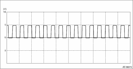
Connector & terminal
No. 13 (+) — No. 42 (−):

(A) | + probe |
(B) | − probe |
3. Start and warm up the engine.
4. Lift up the vehicle.
CAUTION:
Lift up the vehicle until the tire bottom is 0.3 m (0.98 ft) or more above the ground.
5. Shift the select lever to “D” range.
6. Check the waveform and output voltage of the secondary speed sensor with engine idling.
NOTE:
The waveform cycle changes as the speed changes.

 Removal
CONTINUOUSLY VARIABLE TRANSMISSION(TR580) > Secondary Speed SensorREMOVALCAUTION:• Be sure to prevent water or oil from contacting the connector terminal of secondary speed sensor. If adhesio ...
Other materials:
Electrical specification
TIRE PRESSURE MONITORING SYSTEM (DIAGNOSTICS) > Control Module I/O SignalELECTRICAL SPECIFICATIONTerminal No.ContentMeasured value and measuring conditionsRemarks1 — — — 2 — — — 3 — — — 4Ignition power supply10 — 13 V (when the ignition switch is ON) — 5GND0 V (always) ...
Procedure
ENGINE (DIAGNOSTICS)(H4DO) > Malfunction Indicator LightPROCEDURE1. Activation of malfunction indicator light Malfunction Indicator Light > ACTIVATION OF MALFUNCTION INDICATOR LIGHT">↓2. Malfunction indicator light does not come on Malfunction Indicator Light > MALFUNCTION IN ...
Dtc p0617 starter relay "a" circuit high
ENGINE (DIAGNOSTICS)(H4DO) > Diagnostic Procedure with Diagnostic Trouble Code (DTC)DTC P0617 STARTER RELAY "A" CIRCUIT HIGHDTC DETECTING CONDITION:Immediately at fault recognitionTROUBLE SYMPTOM:Failure of engine to startCAUTION:After servicing or replacing faulty parts, perform Clear ...
