Subaru Crosstrek Service Manual: Electrical specification
AUTO HEADLIGHT BEAM LEVELER SYSTEM (DIAGNOSTICS) > Control Module I/O Signal
ELECTRICAL SPECIFICATION
1. AUTO HEADLIGHT BEAM LEVELER CM
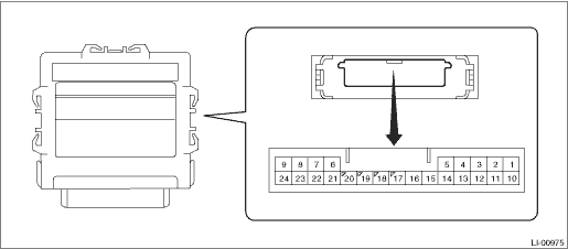
Content | Terminal No. | Measuring condition | Standard |
IG power supply | 1 ←> Chassis ground | Ignition switch ON | 8 — 16 V |
GND | 2 ←> Chassis ground | Always | Less than 1 ? |
Rr vehicle height sensor GND | 3 ←> Chassis ground | Always | Less than 1 ? |
Indicator output | 6 ←> Chassis ground | After turning the ignition switch to ON, for 3 seconds (warning light on) > after 3 seconds (warning light off) | Less than 1.35 V > 8 — 16 V |
Leveling actuator power supply | 10 ←> Chassis ground | Ignition switch ON | 10 — 16 V |
Leveling actuator GND | 11 ←> Chassis ground | Always | Less than 1 ? |
Rr vehicle height sensor power supply | 12 ←> 3 | Ignition switch ON | 4.75 — 5.25 V |
Leveling actuator signal | 17 ←> Chassis ground | Headlight off > on | Less than 1 V > 1.0 — 14.4 V (for 17 seconds) |
Headlight on, no vehicle height change > change and hold vehicle height for 3 seconds or more | |||
Rr sensor signal | 19 ←> Chassis ground | IG ON (with no passenger, no load and vehicle stopped) | Approx. 2.5 V (changes according to vehicle condition) |
CAN-H | 23 | Cannot be measured (CAN communication line) | — |
CAN-L | 24 | Cannot be measured (CAN communication line) | — |

 Wiring diagram
AUTO HEADLIGHT BEAM LEVELER SYSTEM (DIAGNOSTICS) > Control Module I/O SignalWIRING DIAGRAMRefer to “Headlight Beam Leveler System” in the wiring diagram. Headlight Beam Leveler System ...
Other materials:
Installation
BRAKE > Brake BoosterINSTALLATION1. Check and adjust the operating rod of the vacuum booster assembly.(1) Measure the length between the vacuum booster assembly mounting surface and clevis pin hole.(2) If it is not within the specification, loosen the lock nut, rotate the vacuum booster assembly ...
Temperature A, B, C
The temperature grades are A (the
highest), B, and C, representing the
tire's resistance to the generation of
heat and its ability to dissipate heat
when tested under controlled conditions
on a specified indoor laboratory
test wheel. Sustained high
temperature can cause the material
of the t ...
Dtc b2a03 gps antenna circuit
TELEMATICS SYSTEM (DIAGNOSTICS) > Diagnostic Procedure with Diagnostic Trouble Code (DTC)DTC B2A03 GPS ANTENNA CIRCUITDiagnosis start condition:When ignition switch is ON.DTC detecting condition:Any of the followings continues for 5 seconds or more.• GPS antenna impedance is more than 1 M?. ...
