Subaru Crosstrek Service Manual: Electrical component location Location
AIRBAG SYSTEM (DIAGNOSTICS) > Electrical Component Location
LOCATION
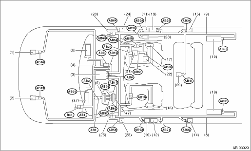
(1) | Front sub sensor (RH) | (11) | Side airbag sensor (RH) | (20) | Satellite safing sensor |
(2) | Front sub sensor (LH) | (12) | Seat belt pretensioner (LH) | (21) | Occupant detection control module |
(3) | Airbag control module | (13) | Seat belt pretensioner (RH) | (22) | Buckle switch (RH) |
(4) | Airbag main harness | (14) | Curtain airbag sensor (LH) | (23) | Front door impact sensor (LH) |
(5) | Roll connector | (15) | Curtain airbag sensor (RH) | (24) | Front door impact sensor (RH) |
(6) | Passenger’s airbag inflator | (16) | Side airbag inflator (LH) | (25) | Door harness (LH) |
(7) | Driver’s airbag inflator | (17) | Side airbag inflator (RH) | (26) | Door harness (RH) |
(8) | Airbag rear harness (LH) | (18) | Curtain airbag inflator (LH) | (27) | Knee airbag inflator |
(9) | Airbag rear harness (RH) | (19) | Curtain airbag inflator (RH) | (28) | Lap seat belt pretensioner (RH) |
(10) | Side airbag sensor (LH) |
Connector No. | (AB1) | (AB2) | (AB6) | (AB7) | (AB9) | (AB13) | (AB16) | (AB17) | (AB18) | (AB19) | (AB21) | (AB23) |
Pin | 10 | 4 | 30 | 4 | 4 | 2 | 2 | 24 | 24 | 4 | 2 | 4 |
Color | Gray | Yellow | Yellow | Yellow | Yellow | Yellow | Yellow | Yellow | Yellow | Yellow | Black | Yellow |
Male/Female | Female | Female | Female | Male | Female | Female | Female | Female | Female | Female | Female | Female |
Connector No. | (AB24) | (AB26) | (AB28) | (AB30) | (AB31) | (AB32) | (AB33) | (AB34) | (AB37) | (AB38) | (AB41) | (AB53) |
Pin | 4 | 2 | 4 | 2 | 2 | 4 | 2 | 4 | 2 | 2 | 2 | 3 |
Color | Yellow | Black | Yellow | Yellow | Black | Yellow | Black | Yellow | Orange | Black | Yellow | Brown |
Male/Female | Female | Female | Female | Female | Female | Female | Female | Female | Female | Female | Female | Female |
Connector No. | (AB58) | (AB59) | (AB60) | (AB61) | (AB62) | (AB63) | (AB64) | (AB66) | ||||
Pin | 2 | 3 | 2 | 10 | 2 | 2 | 2 | 2 | ||||
Color | Yellow | Brown | Yellow | Black | Yellow | Yellow | Yellow | Black | ||||
Male/Female | Female | Male | Male | Female | Female | Female | Female | Female | ||||
 Clear memory mode Operation
AIRBAG SYSTEM (DIAGNOSTICS) > Clear Memory ModeOPERATION1. On «Start» display, select «Diagnosis».2. On «Vehicle selection» display, input the target vehicle information and select «Confirme ...
 Event record data Operation
AIRBAG SYSTEM (DIAGNOSTICS) > Event Record DataOPERATION1. On «Start» display, select «Diagnosis».2. On «Vehicle selection» display, input the target vehicle information and select «Confirme ...
Other materials:
Replacement
CONTINUOUSLY VARIABLE TRANSMISSION(TR580) > CVTFREPLACEMENTCAUTION:• Directly after the vehicle has been running or the engine has been idling for a long time, the CVTF is hot. Be careful not to burn yourself.• Be careful not to spill the CVTF on exhaust pipe to prevent it from emitti ...
Installation
GLASS/WINDOWS/MIRRORS > Front Door GlassINSTALLATIONCAUTION:• Check that the running channel - front door is securely fixed to the panel assembly - front door and to the sash COMPL - partition.• Before installing the glass assembly - front door, check the lip of the running channel - ...
Remote engine start system (dealer
option)
WARNING
There are some general precautions
when starting the engine.
Carefully read the precautions
described in "General precautions
when starting/stopping engine"
F7-9.
Do not remote start a vehicle in
an enclosed environment (e.g.
closed garage). Prolonged operation
of a mot ...
