Subaru Crosstrek Service Manual: Electrical component location Location
EyeSight (DIAGNOSTICS) > Electrical Component Location
LOCATION
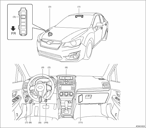
(1) | Stereo camera | (5) | EyeSight steering switch | (9) | Transmission control module (TCM) |
(2) | VDC control module (VDCCM) | (6) | MFD (multi-function display) | (10) | Stop light and brake switch |
(3) | Brake light relay | (7) | Body integrated unit | (11) | ECM |
(4) | Combination meter | (8) | Data link connector |
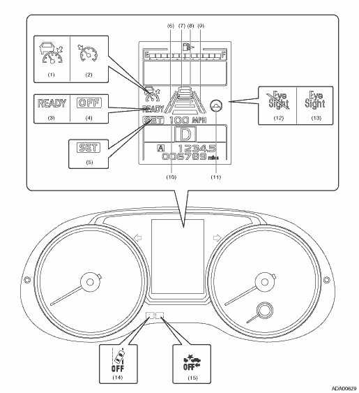
(1) | Adaptive cruise display | (6) | Lane indicator (left) | (11) | Steering wheel indicator |
(2) | Conventional cruise display | (7) | Preceding vehicle indicator | (12) | EyeSight temporary stop indicator |
(3) | READY indicator | (8) | Following distance setting indicator | (13) | EyeSight warning indicator |
(4) | OFF indicator | (9) | Lane indicator (right) | (14) | Lane departure warning OFF indicator light |
(5) | SET indicator | (10) | Set vehicle speed display | (15) | Pre-collision brake OFF indicator light |
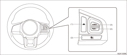
(1) | Following distance setting switch | (3) | RES/+ (resume/plus) switch | (4) | SET/− (set/minus) switch |
(2) | CRUISE switch |
 Clear memory mode Operation
EyeSight (DIAGNOSTICS) > Clear Memory ModeOPERATION1. On «Start» display, select «Diagnosis».2. On «Vehicle selection» display, input the target vehicle information and select «Confirmed».3 ...
 Read current data Operation
EyeSight (DIAGNOSTICS) > Read Current DataOPERATION1. STEREO CAMERA1. On «Start» display, select «Diagnosis».2. On «Vehicle selection» display, input the target vehicle information and select ...
Other materials:
Safety precautions
In the Subaru Ascent, infants and young children must always be seated in an
appropriate child restraint system positioned in the rear seats. This ensures maximum
protection and significantly reduces the risk of injury during sudden stops or collisions.
Always select a child restraint syste ...
Installation
CONTINUOUSLY VARIABLE TRANSMISSION(TR580) > Primary Pulley and Secondary PulleyINSTALLATION1. Select shims for pulley alignment. Primary Pulley and Secondary Pulley > ADJUSTMENT">2. Install the seal ring to the input shaft.NOTE:• Use new seal rings.• When installing the se ...
Inspection
CONTINUOUSLY VARIABLE TRANSMISSION(TR580) > Oil PumpINSPECTIONCheck the following items.• Check the oil pump for damage and wear.• Rotate the oil pump by hand, and check that it rotates smoothly.1. Measure the secondary pressure. Secondary Pressure (Line Pressure) Test > INSPECTIO ...
