Subaru Crosstrek Service Manual: Installation
CONTINUOUSLY VARIABLE TRANSMISSION(TR580) > Primary Pulley and Secondary Pulley
INSTALLATION
1. Select shims for pulley alignment. Primary Pulley and Secondary Pulley > ADJUSTMENT">
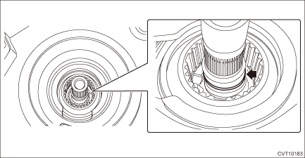
2. Install the seal ring to the input shaft.
NOTE:
• Use new seal rings.
• When installing the seal rings, do not expand the seal rings too much.
• Apply CVTF to the seal rings.
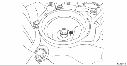
3. Install the seal ring to drive pinion retainer.
NOTE:
• Use new seal rings.
• Apply CVTF to the seal rings.
4. Install the selected shims to the primary pulley bearing catch surface.
5. Install the secondary pulley to the drive pinion retainer.
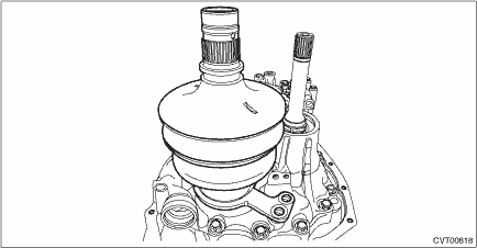
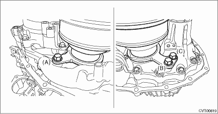
6. Install and tighten the secondary pulley securing bolts.
(1) Tighten the three bolts until the seating surfaces contact the bearing retainer.
NOTE:
• Be careful not to tilt the bearing retainer of the secondary pulley.
• Apply CVTF to the bolt.
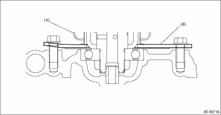
(A) | Secondary pulley |
(B) | Bearing retainer |
(2) Tighten the bolts in the order of (A) > (B) > (C) > (B).
Tightening torque:
67.5 N·m (6.9 kgf-m, 49.8 ft-lb)
7. Place the variator chain on the V groove of the secondary pulley, and set the ST.
| ST 18769AA010 | EXPANDER PULLEY |
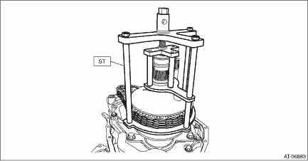
8. Expand the V groove of the secondary pulley.
9. Install the primary pulley to the reverse brake housing together with the variator chain.
CAUTION:
Cover the V grooves of primary pulley and secondary pulley with cloth to protect the both pulleys and variator chain from scratching.
(1) Intersect the V groove of primary pulley and the V groove of secondary pulley and install the secondary pulley while placing the variator chain on secondary pulley.
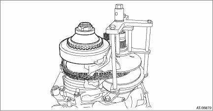
(2) Install the primary pulley to the reverse brake housing so that the bolt hole of primary bearing retainer and the bolt hole of reverse brake housing are aligned.
10. Install the primary pulley bolt.
Tightening torque:
21 N·m (2.1 kgf-m, 15.5 ft-lb)
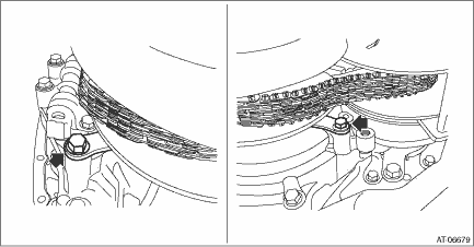
11. Install the chain guide.
(1) Place the support rod inside of the variator chain.
CAUTION:
Protect the both pulleys and variator chain from scratching.
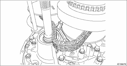
(2) Install the chain guide to the variator chain.
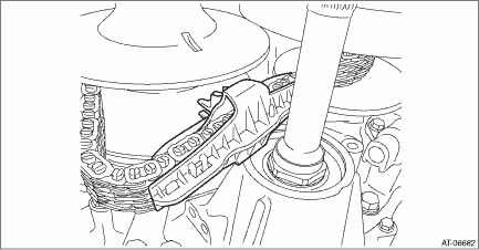
(3) Move the chain guide to the support rod side.
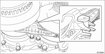
(4) While holding the support rod, press the chain guide so that the support rod runs through between the protrusions of chain guide and install the chain guide to the support rod.
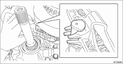
(5) Install the support rod.
Tightening torque:
21 N·m (2.1 kgf-m, 15.5 ft-lb)
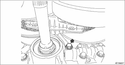
(6) Install the lubrication pipe.
Tightening torque:
21 N·m (2.1 kgf-m, 15.5 ft-lb)
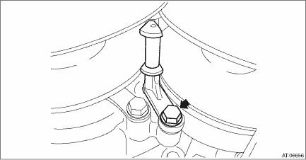
(7) Install the chain guide so that the lubrication pipe runs through between the protrusions of each chain guide. Then remove the ST (PULLEY EXPANDER).
12. Install the reduction drive gear. Reduction Drive Gear > INSTALLATION">
13. Select the reduction drive gear shim. Reduction Drive Gear > ADJUSTMENT">
14. Install the transmission case. Transmission Case > INSTALLATION">
15. Install the transmission control device. Transmission Control Device > INSTALLATION">
16. Install the oil strainer and oil pan. Oil Pan and Strainer > INSTALLATION">
17. Install the reduction driven gear assembly. Reduction Driven Gear > INSTALLATION">
18. Install the transfer driven gear assembly. Transfer Driven Gear > INSTALLATION">
19. Install the transfer clutch assembly. Transfer Clutch > INSTALLATION">
20. Install the parking pawl. Parking Pawl > INSTALLATION">
21. Install the extension case. Extension Case > INSTALLATION">
22. Install the inhibitor switch. Inhibitor Switch > INSTALLATION">
23. Install the secondary speed sensor. Secondary Speed Sensor > INSTALLATION">
24. Install the primary speed sensor. Primary Speed Sensor > INSTALLATION">
25. Install the turbine speed sensor. Turbine Speed Sensor > INSTALLATION">
26. Install the transmission harness. Transmission Harness > INSTALLATION">
27. Install the control valve body. Control Valve Body > INSTALLATION">
28. Install the air breather hose. Air Breather Hose > INSTALLATION">
29. Install the transmission assembly to the vehicle. Automatic Transmission Assembly > INSTALLATION">
 Inspection
CONTINUOUSLY VARIABLE TRANSMISSION(TR580) > Primary Pulley and Secondary PulleyINSPECTION• Check the surface of primary and secondary pulley cones for damage or wear.• Check the primary ...
Other materials:
Adjustment
EXTERIOR BODY PANELS > Front DoorADJUSTMENTAdjust the clearance around the panel assembly - front door as follows.PartStandardAFender COMPL - front to Panel assembly - front door4.5±1.0 mm (0.18±0.04 in)BPanel assembly - front door to Side sill6.0+1.5, −1.0 mm (0.24+0.06, −0.04 in)C ...
Removal
SECURITY AND LOCKS > Front Door Latch and Door Lock Actuator AssemblyREMOVAL1. Raise the glass assembly - front door to the top position.2. Disconnect the ground cable from battery and wait for at least 60 seconds before starting work. NOTE">3. Remove the trim panel - front door. Door T ...
Inspection
SECURITY AND LOCKS > ReceiverINSPECTION1. Check if the door lock operates when the touch sensor of the door outer handle and rear lock button is operated.2. If the system does not operate normally as the result of inspection, refer to “General Diagnostic Table” of the “KEYLESS A ...

