Subaru Crosstrek Service Manual: Dtc p2763 torque converter clutch pressure control solenoid control circuit high
CONTINUOUSLY VARIABLE TRANSMISSION (DIAGNOSTICS) > Diagnostic Procedure with Diagnostic Trouble Code (DTC)
DTC P2763 TORQUE CONVERTER CLUTCH PRESSURE CONTROL SOLENOID CONTROL CIRCUIT HIGH
DTC detecting condition:
Immediately at fault recognition
Trouble symptom:
• No lock-up occurs.
• Engine stalls.
CAUTION:
Use the check board when measuring the TCM terminal voltage and resistance.
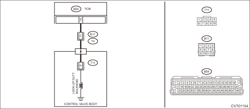
Wiring diagram:
CVT control system CVT Control System">

| STEP | CHECK | YES | NO |
1.CHECK HARNESS.
1) Turn the ignition switch to OFF.
2) Disconnect the TCM connector.
3) Disconnect the transmission connector.
4) Measure the resistance between TCM connector and transmission connectors.
Connector & terminal
(B54) No. 15 — (B11) No. 11:
Is the resistance less than 1 ??
Diagnostic Procedure with Diagnostic Trouble Code (DTC) > DTC P2763 TORQUE CONVERTER CLUTCH PRESSURE CONTROL SOLENOID CONTROL CIRCUIT HIGH">Go to Step 2.
Repair the open circuit of harness.
2.CHECK HARNESS.
1) Turn the ignition switch to ON.
2) Measure the voltage between TCM connector and chassis ground.
Connector & terminal
(B54) No. 15 (+) — Chassis ground (−):
Is the voltage approx. 0 V?
Diagnostic Procedure with Diagnostic Trouble Code (DTC) > DTC P2763 TORQUE CONVERTER CLUTCH PRESSURE CONTROL SOLENOID CONTROL CIRCUIT HIGH">Go to Step 3.
Repair the short circuit of harness.
3.CHECK LOCK-UP DUTY SOLENOID.
Measure the resistance between transmission connector and transmission body.
Connector & terminal
(T4) No. 11 — Transmission body:
Is the resistance approx. 10 — 13.5 ?? (when cold)
Check for poor contact of connector, and if no fault is found, replace the TCM. Transmission Control Module (TCM)">
Diagnostic Procedure with Diagnostic Trouble Code (DTC) > DTC P2763 TORQUE CONVERTER CLUTCH PRESSURE CONTROL SOLENOID CONTROL CIRCUIT HIGH">Go to Step 4.
4.CHECK HARNESS INSIDE TRANSMISSION.
CAUTION:
Start work after ATF cools down.
1) Remove the transmission valve cover.
2) Check for the harness pinch, damage.
Is there any fault in the harness?
Replace the transmission harness.
Diagnostic Procedure with Diagnostic Trouble Code (DTC) > DTC P2763 TORQUE CONVERTER CLUTCH PRESSURE CONTROL SOLENOID CONTROL CIRCUIT HIGH">Go to Step 5.
5.CHECK HARNESS INSIDE TRANSMISSION.
1) Disconnect the control valve body connector.
2) Turn the ignition switch to ON.
3) Measure the voltage between transmission connector and transmission body.
Connector & terminal
(T4) No. 11 (+) — Transmission body (−):
Is the voltage approx. 0 V?
Replace the control valve body. Control Valve Body">
Replace the transmission harness.
1. OUTLINE OF DIAGNOSIS
• Detect short circuit to power supply or open circuit of the lock-up clutch pressure control solenoid drive circuit.
• Judge as NG when an abnormal signal is received from the solenoid driver IC of the lock-up clutch pressure control solenoid drive circuit.
2. EXECUTION CONDITION
Secondary Parameters | Execution condition |
12 V battery system voltage | ≥ 9 V |
Commanded duty of torque converter clutch pressure control solenoid | 0% |
3. DIAGNOSTIC METHOD
If the duration of time while the following conditions are met is longer than the time indicated, judge as NG.
Malfunction Criteria | Threshold Value |
Signal of malfunction from solenoid driver IC | ON |
As defined by: | |
Measured torque converter clutch pressure control solenoid voltage ≥ 2.5 V |
Time Needed for Diagnosis: 0.2 seconds
Malfunction Indicator Light Illumination: Illuminates as soon as a malfunction occurs.
 Dtc p2758 torque converter clutch pressure control solenoid control circuit stuck on
CONTINUOUSLY VARIABLE TRANSMISSION (DIAGNOSTICS) > Diagnostic Procedure with Diagnostic Trouble Code (DTC)DTC P2758 TORQUE CONVERTER CLUTCH PRESSURE CONTROL SOLENOID CONTROL CIRCUIT STUCK ONDTC det ...
 Dtc p2764 torque converter clutch pressure control solenoid control circuit low
CONTINUOUSLY VARIABLE TRANSMISSION (DIAGNOSTICS) > Diagnostic Procedure with Diagnostic Trouble Code (DTC)DTC P2764 TORQUE CONVERTER CLUTCH PRESSURE CONTROL SOLENOID CONTROL CIRCUIT LOWDTC detectin ...
Other materials:
Caution
CONTINUOUSLY VARIABLE TRANSMISSION(TR580) > General DescriptionCAUTION• Remove contamination including dirt and corrosion before removal, installation or disassembly.• Keep the disassembled parts in order and protect them from dust and dirt.• Do not place the valve cover with it ...
Dtc u0122 lost communication with vehicle dynamics control module
KEYLESS ACCESS WITH PUSH BUTTON START SYSTEM (DIAGNOSTICS) > Diagnostic Procedure with Diagnostic Trouble Code (DTC)DTC U0122 LOST COMMUNICATION WITH VEHICLE DYNAMICS CONTROL MODULEDetected when CAN data from VDC does not arrive.NOTE:Perform the diagnosis for LAN system. Basic Diagnostic Procedu ...
Warning and indicator lights
Mark
Name
Seatbelt warning light
Front passenger's
seatbelt warning light
SRS airbag system
warning light
Front passenger's
frontal airbag ON indicator
Front passenger's
frontal airbag OFF indi ...
