Subaru Crosstrek Service Manual: Dtc p0973 shift solenoid "a" control circuit low
CONTINUOUSLY VARIABLE TRANSMISSION (DIAGNOSTICS) > Diagnostic Procedure with Diagnostic Trouble Code (DTC)
DTC P0973 SHIFT SOLENOID "A" CONTROL CIRCUIT LOW
DTC detecting condition:
Immediately at fault recognition
Trouble symptom:
Gear is not changed. (No up-shift)
CAUTION:
Use the check board when measuring the TCM terminal voltage and resistance.
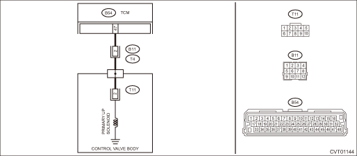
Wiring diagram:
CVT control system CVT Control System">

| STEP | CHECK | YES | NO |
1.CHECK HARNESS.
1) Turn the ignition switch to OFF.
2) Disconnect the TCM connector.
3) Disconnect the transmission connector.
4) Measure the resistance between TCM connector and chassis ground.
Connector & terminal
(B54) No. 47 — Chassis ground:
Is the resistance 1 M? or more?
Diagnostic Procedure with Diagnostic Trouble Code (DTC) > DTC P0973 SHIFT SOLENOID "A" CONTROL CIRCUIT LOW">Go to Step 2.
Repair the short circuit of harness.
2.CHECK PRIMARY UP SOLENOID.
Measure the resistance between transmission connector and transmission body.
Connector & terminal
(T4) No. 2 — Transmission body:
Is the resistance approx. 10 — 13.5 ?? (when cold)
Check for poor contact of connector, and if no fault is found, replace the TCM. Transmission Control Module (TCM)">
Diagnostic Procedure with Diagnostic Trouble Code (DTC) > DTC P0973 SHIFT SOLENOID "A" CONTROL CIRCUIT LOW">Go to Step 3.
3.CHECK HARNESS INSIDE TRANSMISSION.
CAUTION:
Start work after ATF cools down.
1) Remove the transmission valve cover.
2) Check for the harness pinch, damage.
Is there any fault in the harness?
Replace the transmission harness.
Diagnostic Procedure with Diagnostic Trouble Code (DTC) > DTC P0973 SHIFT SOLENOID "A" CONTROL CIRCUIT LOW">Go to Step 4.
4.CHECK HARNESS INSIDE TRANSMISSION.
1) Disconnect the control valve body connector.
2) Measure the resistance between transmission connector and transmission body.
Connector & terminal
(T4) No. 2 — Transmission body:
Is the resistance 1 M? or more?
Replace the control valve body. Control Valve Body">
Replace the transmission harness.
1. OUTLINE OF DIAGNOSIS
• Detect the ground short of the shift-up fluid pressure control solenoid drive circuit.
• Judge as NG when an abnormal signal is received from the solenoid driver IC of the shift-up fluid pressure control solenoid drive circuit.
2. EXECUTION CONDITION
Secondary Parameters | Execution condition |
12 V battery system voltage | ≥ 9 V |
Commanded duty of shift up pressure control solenoid | 100% |
3. DIAGNOSTIC METHOD
If the duration of time while the following conditions are met is longer than the time indicated, judge as NG.
Malfunction Criteria | Threshold Value |
Signal of malfunction from solenoid driver IC | ON |
As defined by: | |
Measured shift up pressure control solenoid voltage ≤ 0.8 V |
Time Needed for Diagnosis: 0.2 seconds
Malfunction Indicator Light Illumination: Illuminates as soon as a malfunction occurs.
 Dtc p0971 pressure control solenoid "c" control circuit high
CONTINUOUSLY VARIABLE TRANSMISSION (DIAGNOSTICS) > Diagnostic Procedure with Diagnostic Trouble Code (DTC)DTC P0971 PRESSURE CONTROL SOLENOID "C" CONTROL CIRCUIT HIGHDTC detecting conditi ...
 Dtc p0974 shift solenoid "a" control circuit high
CONTINUOUSLY VARIABLE TRANSMISSION (DIAGNOSTICS) > Diagnostic Procedure with Diagnostic Trouble Code (DTC)DTC P0974 SHIFT SOLENOID "A" CONTROL CIRCUIT HIGHDTC detecting condition:Immediat ...
Other materials:
Dtc b1812 short in driver s airbag dual stage - 2nd step (to ground)
AIRBAG SYSTEM (DIAGNOSTICS) > Diagnostic Chart with Trouble CodeDTC B1812 SHORT IN DRIVER’S AIRBAG DUAL STAGE - 2ND STEP (TO GROUND)Diagnosis start condition:Ignition voltage is 10 V to 16 V.DTC detecting condition:• Airbag main harness circuit is shorted to ground.• Airbag modu ...
Installation
AIRBAG SYSTEM > Knee Airbag ModuleINSTALLATIONCAUTION:• Before handling the airbag system components, refer to “CAUTION” of “General Description” in “AIRBAG SYSTEM”. General Description > CAUTION">• Do not allow harness and connectors to ...
Operation
EyeSight (DIAGNOSTICS) > EyeSight Temporary Code(s) DisplayOPERATIONIf the EyeSight pause code is detected from the stereo camera, all the functions of the EyeSight excluding the conventional cruise control stop temporarily and cannot be used. When the failure is resolved, the function starts ope ...
