Subaru Crosstrek Service Manual: Dtc p0963 pressure control solenoid "a" control circuit high
CONTINUOUSLY VARIABLE TRANSMISSION (DIAGNOSTICS) > Diagnostic Procedure with Diagnostic Trouble Code (DTC)
DTC P0963 PRESSURE CONTROL SOLENOID "A" CONTROL CIRCUIT HIGH
DTC detecting condition:
Immediately at fault recognition
Trouble symptom:
• Engine speed increases abruptly, and can not start.
• Engine speed increases abruptly during driving.
CAUTION:
Use the check board when measuring the TCM terminal voltage and resistance.
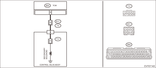
Wiring diagram:
CVT control system CVT Control System">

| STEP | CHECK | YES | NO |
1.CHECK INPUT SIGNAL FOR TCM.
1) After driving with warm up condition, park the vehicle while depressing the brake pedal at “N” range.
2) Read the data of «Secondary Set Current» and «Secondary Actual Current» using Subaru Select Monitor.
Does the value of «Secondary Set Current» and «Secondary Actual Current» almost correspond?
Check for poor contact of connector.
Diagnostic Procedure with Diagnostic Trouble Code (DTC) > DTC P0963 PRESSURE CONTROL SOLENOID "A" CONTROL CIRCUIT HIGH">Go to Step 2.
2.CHECK HARNESS.
1) Turn the ignition switch to OFF.
2) Disconnect the TCM connector.
3) Disconnect the transmission connector.
4) Measure the resistance between TCM connector and transmission connectors.
Connector & terminal
(B54) No. 32 — (B11) No. 6:
Is the resistance less than 1 ??
Diagnostic Procedure with Diagnostic Trouble Code (DTC) > DTC P0963 PRESSURE CONTROL SOLENOID "A" CONTROL CIRCUIT HIGH">Go to Step 3.
Repair the open circuit of harness.
3.CHECK HARNESS.
1) Turn the ignition switch to ON.
2) Measure the voltage between TCM connector and chassis ground.
Connector & terminal
(B54) No. 32 (+) — Chassis ground (−):
Is the voltage approx. 0 V?
Diagnostic Procedure with Diagnostic Trouble Code (DTC) > DTC P0963 PRESSURE CONTROL SOLENOID "A" CONTROL CIRCUIT HIGH">Go to Step 4.
Repair the short circuit of harness.
4.CHECK SECONDARY SOLENOID.
Measure the resistance between transmission connector and transmission body.
Connector & terminal
(T4) No. 6 — Transmission body:
Is the resistance approx. 5 — 7 ?? (when cold)
Check for poor contact of connector, and if no fault is found, replace the TCM. Transmission Control Module (TCM)">
Diagnostic Procedure with Diagnostic Trouble Code (DTC) > DTC P0963 PRESSURE CONTROL SOLENOID "A" CONTROL CIRCUIT HIGH">Go to Step 5.
5.CHECK HARNESS INSIDE TRANSMISSION.
CAUTION:
Start work after ATF cools down.
1) Remove the transmission valve cover.
2) Check for the harness pinch, damage.
Is there any fault in the harness?
Replace the transmission harness.
Diagnostic Procedure with Diagnostic Trouble Code (DTC) > DTC P0963 PRESSURE CONTROL SOLENOID "A" CONTROL CIRCUIT HIGH">Go to Step 6.
6.CHECK HARNESS INSIDE TRANSMISSION.
1) Disconnect the control valve body connector.
2) Turn the ignition switch to ON.
3) Measure the voltage between transmission connector and transmission body.
Connector & terminal
(T4) No. 6 (+) — Transmission body (−):
Is the voltage approx. 0 V?
Replace the control valve body. Control Valve Body">
Replace the transmission harness.
1. OUTLINE OF DIAGNOSIS
• Detect short circuit to power supply or open circuit of the transmission line pressure solenoid drive circuit.
• Judge as NG if the transmission line pressure solenoid drive current is lower than the predetermined value.
2. EXECUTION CONDITION
Secondary Parameters | Execution condition |
12 V battery system voltage | ≥ 9 V |
Commanded line pressure control solenoid valve current | ≥ 0.2 A |
3. DIAGNOSTIC METHOD
If the duration of time while the following conditions are met is longer than the time indicated, judge as NG.
Malfunction Criteria | Threshold Value |
Measured line pressure control solenoid valve current | < 0.1 A |
Time Needed for Diagnosis: 0.5 seconds
Malfunction Indicator Light Illumination: Illuminates as soon as a malfunction occurs.
 Dtc p0962 pressure control solenoid "a" control circuit low
CONTINUOUSLY VARIABLE TRANSMISSION (DIAGNOSTICS) > Diagnostic Procedure with Diagnostic Trouble Code (DTC)DTC P0962 PRESSURE CONTROL SOLENOID "A" CONTROL CIRCUIT LOWDTC detecting conditio ...
 Dtc p0965 pressure control solenoid "b" control circuit range/performance
CONTINUOUSLY VARIABLE TRANSMISSION (DIAGNOSTICS) > Diagnostic Procedure with Diagnostic Trouble Code (DTC)DTC P0965 PRESSURE CONTROL SOLENOID "B" CONTROL CIRCUIT RANGE/PERFORMANCEDTC DETE ...
Other materials:
Hazard warning flasher setting
1. Perform the preparation steps according
to "Preparation for car settings"
2. Operate the " " or "
" switch to
select the "Hazard Warning Flasher" item.Then push the button.
3. The current setting will be displayed.
Push the button to enter the
selection
mode.
4. Select "O ...
11
CRUISE CONTROL SYSTEM (DIAGNOSTICS) > Diagnostic Procedure with Cancel Code11When CRUISE switch is pressed, or a malfunction related to CRUISE switch occurs, this is detected.Trouble symptom:• Cruise control cannot be set. (Cancelled immediately.)• Cruise control cannot be released.Wi ...
Dtc u1120 lost communication with autostart stop control module
LAN SYSTEM (DIAGNOSTICS) > Diagnostic Procedure with Diagnostic Trouble Code (DTC)DTC U1120 LOST COMMUNICATION WITH AUTOSTART STOP CONTROL MODULENOTE:The electric power steering CM identifies whether the Auto Start Stop function is provided or not using information from the combination meter. The ...
