Subaru Crosstrek Service Manual: Dtc p0841 transmission fluid pressure sensor/switch "a" circuit range/performance
CONTINUOUSLY VARIABLE TRANSMISSION (DIAGNOSTICS) > Diagnostic Procedure with Diagnostic Trouble Code (DTC)
DTC P0841 TRANSMISSION FLUID PRESSURE SENSOR/SWITCH "A" CIRCUIT RANGE/PERFORMANCE
DTC detecting condition:
Immediately at fault recognition
Trouble symptom:
• Acceleration is poor during standing start.
• Shift control malfunction
• Engine speed increases abruptly.
CAUTION:
• Before performing diagnosis, record the freeze frame data.
• Use the check board when measuring the TCM terminal voltage and resistance.
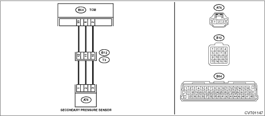
Wiring diagram:
CVT control system CVT Control System">

| STEP | CHECK | YES | NO |
1.CHECK DTC.
Read the DTC using Subaru Select Monitor.
Are DTCs other than P0841 displayed?
Perform the diagnosis according to DTC. After the diagnosis, start the engine, and drive for 20 minutes in any driving pattern. (Include driving at a constant legal speed (for 20 seconds) at least once.) Read the DTC, and if P0841 alone is detected, Diagnostic Procedure with Diagnostic Trouble Code (DTC) > DTC P0841 TRANSMISSION FLUID PRESSURE SENSOR/SWITCH "A" CIRCUIT RANGE/PERFORMANCE">Go to Step 2.
Diagnostic Procedure with Diagnostic Trouble Code (DTC) > DTC P0841 TRANSMISSION FLUID PRESSURE SENSOR/SWITCH "A" CIRCUIT RANGE/PERFORMANCE">Go to Step 2.
2.CHECK INPUT SIGNAL FOR TCM.
1) Turn the ignition switch to ON.
2) Read the data of «secondary pressure sensor voltage.» using Subaru Select Monitor. (While shaking the secondary pressure sensor harness)
Is the value of «secondary pressure sensor voltage» 0.39 — 0.61 V?
Diagnostic Procedure with Diagnostic Trouble Code (DTC) > DTC P0841 TRANSMISSION FLUID PRESSURE SENSOR/SWITCH "A" CIRCUIT RANGE/PERFORMANCE">Go to Step 10.
Diagnostic Procedure with Diagnostic Trouble Code (DTC) > DTC P0841 TRANSMISSION FLUID PRESSURE SENSOR/SWITCH "A" CIRCUIT RANGE/PERFORMANCE">Go to Step 3.
3.CHECK HARNESS.
1) Turn the ignition switch to OFF.
2) Disconnect the connector of TCM and secondary pressure sensor.
3) Measure the resistance between TCM connector and secondary pressure sensor connector.
Connector & terminal
(B54) No. 2 — (AT6) No. 3:
(B54) No. 5 — (AT6) No. 2:
(B54) No. 33 — (AT6) No. 1:
Is the resistance less than 1 ??
Diagnostic Procedure with Diagnostic Trouble Code (DTC) > DTC P0841 TRANSMISSION FLUID PRESSURE SENSOR/SWITCH "A" CIRCUIT RANGE/PERFORMANCE">Go to Step 4.
Repair the open circuit of harness.
4.CHECK HARNESS.
Measure the resistance between TCM connectors.
Connector & terminal
(B54) No. 2 — (B54) No. 33:
(B54) No. 5 — (B54) No. 2:
(B54) No. 33 — (B54) No. 5:
Is the resistance 1 M? or more?
Diagnostic Procedure with Diagnostic Trouble Code (DTC) > DTC P0841 TRANSMISSION FLUID PRESSURE SENSOR/SWITCH "A" CIRCUIT RANGE/PERFORMANCE">Go to Step 5.
Repair the short circuit of harness.
5.CHECK HARNESS.
Measure the resistance between TCM connector and transmission body.
Connector & terminal
(B54) No. 2 — Transmission body:
(B54) No. 5 — Transmission body:
(B54) No. 33 — Transmission body:
Is the resistance 1 M? or more?
Diagnostic Procedure with Diagnostic Trouble Code (DTC) > DTC P0841 TRANSMISSION FLUID PRESSURE SENSOR/SWITCH "A" CIRCUIT RANGE/PERFORMANCE">Go to Step 6.
Repair the short circuit of harness.
6.CHECK POWER SUPPLY FOR SECONDARY PRESSURE SENSOR.
1) Turn the ignition switch to ON.
2) Measure the voltage between TCM connectors.
Connector & terminal
(B54) No. 33 (+) — (B54) No. 2 (−):
Is the voltage 4.6 — 5.4 V?
Diagnostic Procedure with Diagnostic Trouble Code (DTC) > DTC P0841 TRANSMISSION FLUID PRESSURE SENSOR/SWITCH "A" CIRCUIT RANGE/PERFORMANCE">Go to Step 7.
Check for poor contact of connector, and if no fault is found, replace the TCM. Transmission Control Module (TCM)">
7.CHECK POWER SUPPLY FOR SECONDARY PRESSURE SENSOR.
1) Turn the ignition switch to OFF.
2) Connect the secondary pressure sensor connector.
3) Turn the ignition switch to ON.
4) Measure the voltage between TCM connectors.
Connector & terminal
(B54) No. 33 (+) — (B54) No. 2 (−):
Is the voltage 4.6 — 5.4 V?
Diagnostic Procedure with Diagnostic Trouble Code (DTC) > DTC P0841 TRANSMISSION FLUID PRESSURE SENSOR/SWITCH "A" CIRCUIT RANGE/PERFORMANCE">Go to Step 8.
Replace the secondary pressure sensor. Secondary Pressure Sensor">
8.CHECK SECONDARY PRESSURE SENSOR OUTPUT.
Measure the voltage between TCM connectors.
Connector & terminal
(B54) No. 5 (+) — (B54) No. 2 (−):
Is the voltage 0.39 — 0.61 V?
Check for poor contact of connector, and if no fault is found, replace the TCM. Transmission Control Module (TCM)">
Diagnostic Procedure with Diagnostic Trouble Code (DTC) > DTC P0841 TRANSMISSION FLUID PRESSURE SENSOR/SWITCH "A" CIRCUIT RANGE/PERFORMANCE">Go to Step 9.
9.CHECK CONNECTOR.
1) Turn the ignition switch to OFF.
2) Disconnect the connector of TCM and secondary pressure sensor.
3) Check the TCM connector (B54) and the secondary pressure sensor connector (AT6).
Is there any fault in the TCM connector or the secondary pressure connector?
Repair the connector, or replace harness.
Diagnostic Procedure with Diagnostic Trouble Code (DTC) > DTC P0841 TRANSMISSION FLUID PRESSURE SENSOR/SWITCH "A" CIRCUIT RANGE/PERFORMANCE">Go to Step 10.
10.CHECK TRANSMISSION FLUID.
1) Connect all connectors.
2) Check the amount of ATF. CVTF > ADJUSTMENT">
Is the check result OK?
Diagnostic Procedure with Diagnostic Trouble Code (DTC) > DTC P0841 TRANSMISSION FLUID PRESSURE SENSOR/SWITCH "A" CIRCUIT RANGE/PERFORMANCE">Go to Step 11.
Adjust the amount of ATF. CVTF > ADJUSTMENT"> Diagnostic Procedure with Diagnostic Trouble Code (DTC) > DTC P0841 TRANSMISSION FLUID PRESSURE SENSOR/SWITCH "A" CIRCUIT RANGE/PERFORMANCE">Go to Step 11.
11.CHECK INPUT SIGNAL FOR TCM.
1) Perform the Clear Memory Mode.
2) Start the engine.
3) Warm up until the ATF temperature reaches to 40 — 70°C (104 — 158°F).
4) Depress the brake pedal and move the select lever to each range at an interval of five seconds.
NOTE:
Move the select lever in the following order: “P” > “R” > “N” > “D” > “N” > “R” > “P”.
5) Stabilize the engine speed at idle.
6) Read the data of «Actual Secondary Pressure» using Subaru Select Monitor.
Is the «Actual Secondary Pressure» 0.5 — 1.5 MPa?
Diagnostic Procedure with Diagnostic Trouble Code (DTC) > DTC P0841 TRANSMISSION FLUID PRESSURE SENSOR/SWITCH "A" CIRCUIT RANGE/PERFORMANCE">Go to Step 12.
Replace the secondary pressure sensor. Secondary Pressure Sensor">
12.CHECK INPUT SIGNAL FOR TCM.
1) Shift the select lever to “P” range.
2) Keep the engine speed at 3,000 rpm.
3) Read the data of «Actual Secondary Pressure» using Subaru Select Monitor.
Is the «Actual Secondary Pressure» 1.5 — 2.5 MPa? And is the difference of the actual oil pressure 0.2 MPa or more compared with the value measured in step 11?
Diagnostic Procedure with Diagnostic Trouble Code (DTC) > DTC P0841 TRANSMISSION FLUID PRESSURE SENSOR/SWITCH "A" CIRCUIT RANGE/PERFORMANCE">Go to Step 13.
Replace the secondary pressure sensor. Secondary Pressure Sensor">
13.CHECK FREEZE FRAME DATA.
1) Turn the ignition switch to OFF.
2) Check the recorded freeze frame data.
Was the detected symptom low-voltage malfunction? Diagnostic Procedure with Diagnostic Trouble Code (DTC) > DTC P0841 TRANSMISSION FLUID PRESSURE SENSOR/SWITCH "A" CIRCUIT RANGE/PERFORMANCE">
Replace the transmission assembly. Automatic Transmission Assembly">
Diagnostic Procedure with Diagnostic Trouble Code (DTC) > DTC P0841 TRANSMISSION FLUID PRESSURE SENSOR/SWITCH "A" CIRCUIT RANGE/PERFORMANCE">Go to Step 14.
14.CHECK TCM INPUT SIGNAL (STALL TEST).
1) Lift up the vehicle.
2) Start the engine.
3) Apply the parking brake.
4) Set the select lever to “D” range.
5) Depress the brake pedal firmly.
6) Slowly open the accelerator fully, and stabilize the engine speed.
7) Read the data of «Actual Secondary Pressure» using Subaru Select Monitor.
Is the «Actual Secondary Pressure» 4.5 — 6.0 MPa?
Replace the transmission assembly. Automatic Transmission Assembly">
Diagnostic Procedure with Diagnostic Trouble Code (DTC) > DTC P0841 TRANSMISSION FLUID PRESSURE SENSOR/SWITCH "A" CIRCUIT RANGE/PERFORMANCE">Go to Step 15.
15.CHECK TCM INPUT SIGNAL (STALL TEST).
Check the «Actual Secondary Pressure» in step 14.
Is the «Actual Secondary Pressure» 4.5 MPa or less?
Replace the transmission assembly. Automatic Transmission Assembly">
Replace the control valve body. Control Valve Body">
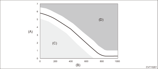
1. CLASSIFICATION OF SYMPTOM USING FREEZE FRAME DATA
Apply the values of «Actual Secondary Pressure» and «Secondary Actual Current» recorded in the freeze frame data onto the graph shown in the following figure, and judge if either low-voltage malfunction or high-voltage malfunction occurs.

(A) | Actual secondary pressure (MPa) | (C) | Low-voltage malfunction | (D) | High-voltage malfunction |
(B) | Secondary actual current (mA) |
NOTE:
Symptom that the DTC P0841 illuminates can be classified into 2 patterns.
• Low-voltage malfunction: detected due to insufficient oil pressure
• High-voltage malfunction: detected due to excessive oil pressure
2. OUTLINE OF DIAGNOSIS
• Detect the malfunction of transmission fluid pressure control function.
• Judge as NG if a discrepancy between the target secondary oil pressure (as internal data) and the detected value of the secondary oil pressure sensor becomes the specified value or more.
3. EXECUTION CONDITION
Secondary parameters | Execution condition |
12 V battery system voltage | ≥ 10 V |
Engine speed | ≥ Table 1 rpm |
Target line pressure (kPa) | 0 | 500 | 1000 | 1500 | 2000 | 3000 | 4000 | 5000 | 6000 |
Engine speed (rpm) | 300 | 660 | 900 | 1080 | 1170 | 1400 | 1680 | 1900 | 2100 |
4. DIAGNOSTIC METHOD
If the duration of time while the following conditions are met is longer than the time indicated, judge as NG.
Malfunction Criteria | Threshold Value |
|Target line pressure − Measured line pressure| | ≥ 500 kPa |
Time Needed for Diagnosis: 5 seconds
Malfunction Indicator Light Illumination: Illuminates as soon as a malfunction occurs.
 Dtc p0801 reverse inhibit control circuit/open
CONTINUOUSLY VARIABLE TRANSMISSION (DIAGNOSTICS) > Diagnostic Procedure with Diagnostic Trouble Code (DTC)DTC P0801 REVERSE INHIBIT CONTROL CIRCUIT/OPENDTC DETECTING CONDITION:Immediately at fault ...
 Dtc p0842 transmission fluid pressure sensor/switch "a" circuit low
CONTINUOUSLY VARIABLE TRANSMISSION (DIAGNOSTICS) > Diagnostic Procedure with Diagnostic Trouble Code (DTC)DTC P0842 TRANSMISSION FLUID PRESSURE SENSOR/SWITCH "A" CIRCUIT LOWDTC detecting ...
Other materials:
Dtc c0045 tcm malfunction
VEHICLE DYNAMICS CONTROL (VDC) (DIAGNOSTICS) > Diagnostic Procedure with Diagnostic Trouble Code (DTC)DTC C0045 TCM MALFUNCTIONDTC detecting condition:Defective TCMTrouble symptom:• ABS does not operate.• VDC does not operate.• EyeSight does not operate.STEPCHECKYESNO1.CHECK CVT ...
Cvt control system Wiring diagram
WIRING SYSTEM > CVT Control SystemWIRING DIAGRAM ...
Installation
AIRBAG SYSTEM > Curtain Airbag SensorINSTALLATIONCAUTION:• Do not reuse the bolt and nut.Always replace with the specified new bolts and nuts.• When installing the sensor, insert the set pin on the backside of the sensor into the hole on the body side securely.1. Before installation, ...
