Subaru Crosstrek Service Manual: Dtc p0459 evap system (cpc) purge control valve "a" circuit high
ENGINE (DIAGNOSTICS)(H4DO) > Diagnostic Procedure with Diagnostic Trouble Code (DTC)
DTC P0459 EVAP SYSTEM (CPC) PURGE CONTROL VALVE "A" CIRCUIT HIGH
DTC detecting condition:
Detected when two consecutive driving cycles with fault occur.
Trouble symptom:
Improper idling
CAUTION:
After servicing or replacing faulty parts, perform Clear Memory Mode Clear Memory Mode > OPERATION"> , and Inspection Mode Inspection Mode > PROCEDURE">.
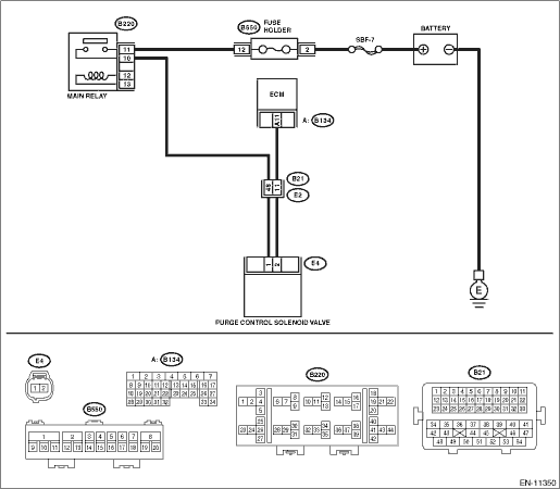
Wiring diagram:
Engine electrical system Engine Electrical System">
| STEP | CHECK | YES | NO |
1.CHECK HARNESS BETWEEN ECM AND PURGE CONTROL SOLENOID VALVE CONNECTOR.
1) Turn the ignition switch to OFF.
2) Disconnect the connector from ECM.
3) Disconnect the connector from the purge control solenoid valve.
4) Turn the ignition switch to ON.
5) Measure the voltage between ECM connector and chassis ground.
Connector & terminal
(B134) No. 11 (+) — Chassis ground (−):
Is the voltage 10 V or more?
Repair the short circuit to power in the harness between ECM connector and purge control solenoid valve connector.
Diagnostic Procedure with Diagnostic Trouble Code (DTC) > DTC P0459 EVAP SYSTEM (CPC) PURGE CONTROL VALVE "A" CIRCUIT HIGH">Go to Step 2.
2.CHECK PURGE CONTROL SOLENOID VALVE.
1) Turn the ignition switch to OFF.
2) Measure the resistance between purge control solenoid valve terminals.
Terminals
No. 1 — No. 2:
Is the resistance less than 1 ??
Replace the purge control solenoid valve. Purge Control Solenoid Valve">
Repair the poor contact of ECM connector.
1. OUTLINE OF DIAGNOSIS
Detect open or short circuit of the purge control solenoid valve.
Judge as NG when the ECM output level differs from the actual terminal level.
2. COMPONENT DESCRIPTION
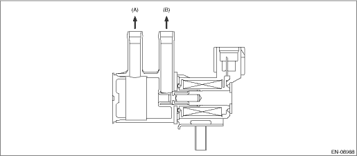
(A) | To canister | (B) | To intake manifold |
3. EXECUTION CONDITION
Secondary Parameters | Execution condition |
12 V battery system voltage | ≥ 10.9 V |
Purge control duty ratio | ≥ 25% |
4. GENERAL DRIVING CYCLE
Always perform the diagnosis after starting the engine.
5. DIAGNOSTIC METHOD
If the duration of time while the following conditions are met is longer than the time indicated, judge as NG.
Malfunction Criteria | Threshold Value |
Measured solenoid valve for purge control current | ≥ 12 A |
Time Needed for Diagnosis: 2500 ms
Malfunction Indicator Light Illumination: Illuminates when malfunction occurs in 2 continuous driving cycles.
 Dtc p0458 evap system (cpc) purge control valve "a" circuit low
ENGINE (DIAGNOSTICS)(H4DO) > Diagnostic Procedure with Diagnostic Trouble Code (DTC)DTC P0458 EVAP SYSTEM (CPC) PURGE CONTROL VALVE "A" CIRCUIT LOWDTC detecting condition:Detected when tw ...
 Dtc p0500 vehicle speed sensor "a" circuit
ENGINE (DIAGNOSTICS)(H4DO) > Diagnostic Procedure with Diagnostic Trouble Code (DTC)DTC P0500 VEHICLE SPEED SENSOR "A" CIRCUITDTC DETECTING CONDITION:Immediately at fault recognitionCAUTI ...
Other materials:
Installation
ENTERTAINMENT > GPS AntennaINSTALLATIONCAUTION:• After installing the center grille assembly, check that the air vent grille of the center grille assembly is inserted correctly into the air vent duct.• Before handling the airbag system components, always refer to “CAUTION” ...
Component
STARTING/CHARGING SYSTEMS(H4DO) > General DescriptionCOMPONENT1. STARTER(1)Starter housing ASSY(9)Overrunning clutch(17)Sleeve bearing(2)Sleeve bearing(10)Internal gear ASSY(18)Starter cover ASSY(3)Shift lever(11)Shaft (4)Plate(12)Pinion gearTightening torque: N·m (kgf-m, ft-lb)(5)Seal rub ...
Dtc c1311 fr hold valve
VEHICLE DYNAMICS CONTROL (VDC) (DIAGNOSTICS) > Diagnostic Procedure with Diagnostic Trouble Code (DTC)DTC C1311 FR HOLD VALVENOTE:For the diagnostic procedure, refer to “DTC C1362 NORMAL CLOSING VALVE 2”. Diagnostic Procedure with Diagnostic Trouble Code (DTC) > DTC C1362 NORMAL C ...
