Subaru Crosstrek Service Manual: Dtc p0458 evap system (cpc) purge control valve "a" circuit low
ENGINE (DIAGNOSTICS)(H4DO) > Diagnostic Procedure with Diagnostic Trouble Code (DTC)
DTC P0458 EVAP SYSTEM (CPC) PURGE CONTROL VALVE "A" CIRCUIT LOW
DTC detecting condition:
Detected when two consecutive driving cycles with fault occur.
Trouble symptom:
Improper idling
CAUTION:
After servicing or replacing faulty parts, perform Clear Memory Mode Clear Memory Mode > OPERATION"> , and Inspection Mode Inspection Mode > PROCEDURE">.
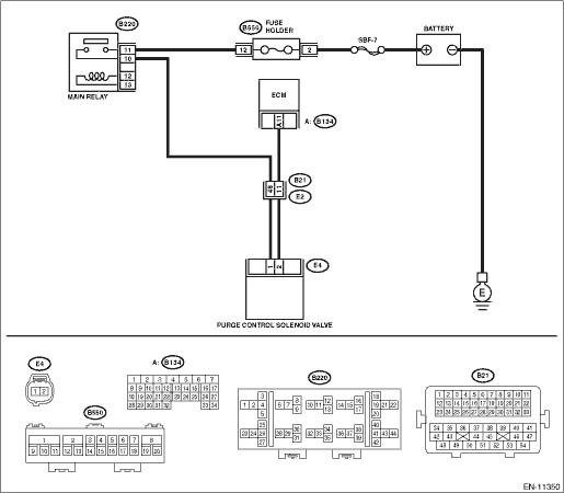
Wiring diagram:
Engine electrical system Engine Electrical System">
| STEP | CHECK | YES | NO |
1.CHECK OUTPUT SIGNAL OF ECM.
1) Turn the ignition switch to ON.
2) Measure the voltage between ECM connector and chassis ground.
Connector & terminal
(B137) No. 6 (+) — Chassis ground (−):
Is the voltage 10 V or more?
Diagnostic Procedure with Diagnostic Trouble Code (DTC) > DTC P0458 EVAP SYSTEM (CPC) PURGE CONTROL VALVE "A" CIRCUIT LOW">Go to Step 2.
Diagnostic Procedure with Diagnostic Trouble Code (DTC) > DTC P0458 EVAP SYSTEM (CPC) PURGE CONTROL VALVE "A" CIRCUIT LOW">Go to Step 3.
2.CHECK FOR POOR CONTACT.
Check for poor contact of ECM connector.
Is there poor contact of ECM connector?
Repair the poor contact of ECM connector.
Even if DTC is detected, the circuit has returned to a normal condition at this time. Reproduce the failure, and then perform the diagnosis again.
NOTE:
In this case, temporary open or short circuit of harness or temporary poor contact of connector may be the cause.
3.CHECK POWER SUPPLY TO PURGE CONTROL SOLENOID VALVE.
Measure the voltage between purge control solenoid valve connector and engine ground.
Connector & terminal
(E4) No. 1 (+) — Engine ground (−):
Is the voltage 10 V or more?
Diagnostic Procedure with Diagnostic Trouble Code (DTC) > DTC P0458 EVAP SYSTEM (CPC) PURGE CONTROL VALVE "A" CIRCUIT LOW">Go to Step 4.
Repair the power supply circuit.
4.CHECK HARNESS BETWEEN ECM AND PURGE CONTROL SOLENOID VALVE CONNECTOR.
1) Turn the ignition switch to OFF.
2) Disconnect the connector from ECM.
3) Disconnect the connector from the purge control solenoid valve.
4) Measure the resistance between the purge control solenoid valve connector and engine ground.
Connector & terminal
(E4) No. 2 — Engine ground:
Is the resistance 1 M? or more?
Diagnostic Procedure with Diagnostic Trouble Code (DTC) > DTC P0458 EVAP SYSTEM (CPC) PURGE CONTROL VALVE "A" CIRCUIT LOW">Go to Step 5.
Repair the short circuit to ground in harness between ECM connector and purge control solenoid valve connector.
5.CHECK HARNESS BETWEEN ECM AND PURGE CONTROL SOLENOID VALVE CONNECTOR.
Measure the resistance of harness between ECM connector and purge control solenoid valve.
Connector & terminal
(B134) No. 11 — (E4) No. 2:
Is the resistance less than 1 ??
Diagnostic Procedure with Diagnostic Trouble Code (DTC) > DTC P0458 EVAP SYSTEM (CPC) PURGE CONTROL VALVE "A" CIRCUIT LOW">Go to Step 6.
Repair the harness and connector.
NOTE:
In this case, repair the following item:
• Open circuit in harness between ECM connector and purge control solenoid valve connector
• Poor contact of coupling connector
6.CHECK PURGE CONTROL SOLENOID VALVE.
1) Remove the purge control solenoid valve.
2) Measure the resistance between purge control solenoid valve terminals.
Terminals
No. 1 — No. 2:
Is the resistance 10 — 100 ??
Repair the poor contact of purge control solenoid valve connector.
Replace the purge control solenoid valve. Purge Control Solenoid Valve">
1. OUTLINE OF DIAGNOSIS
Detect open or short circuit of the purge control solenoid valve.
Judge as NG when the ECM output level differs from the actual terminal level.
2. COMPONENT DESCRIPTION
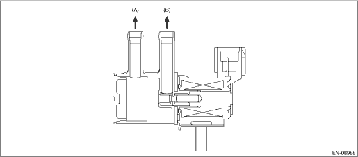
(A) | To canister | (B) | To intake manifold |
3. EXECUTION CONDITION
Secondary Parameters | Execution condition |
12 V battery system voltage | ≥ 10.9 V |
Purge control duty ratio | < 75% |
4. GENERAL DRIVING CYCLE
Always perform the diagnosis after starting the engine.
5. DIAGNOSTIC METHOD
If the duration of time while the following conditions are met is longer than the time indicated, judge as NG.
Malfunction Criteria | Threshold Value |
Measured solenoid valve for purge control voltage | ≤ 12 V battery system voltage ? 0.34 V |
Time Needed for Diagnosis: 2500 ms
Malfunction Indicator Light Illumination: Illuminates when malfunction occurs in 2 continuous driving cycles.
 Dtc p0456 evap system (cpc) leak detected (very small leak)
ENGINE (DIAGNOSTICS)(H4DO) > Diagnostic Procedure with Diagnostic Trouble Code (DTC)DTC P0456 EVAP SYSTEM (CPC) LEAK DETECTED (VERY SMALL LEAK)NOTE:For the diagnostic procedure, refer to DTC P0455. ...
 Dtc p0459 evap system (cpc) purge control valve "a" circuit high
ENGINE (DIAGNOSTICS)(H4DO) > Diagnostic Procedure with Diagnostic Trouble Code (DTC)DTC P0459 EVAP SYSTEM (CPC) PURGE CONTROL VALVE "A" CIRCUIT HIGHDTC detecting condition:Detected when t ...
Other materials:
Inspection
GLASS/WINDOWS/MIRRORS > Remote Control Mirror SystemINSPECTION1. SYMPTOM CHARTSymptomsInspection orderAll function does not operate.(1) Check the fuse.(2) Check the remote control mirror switch.(3) Check the wiring harness.One side of the mirror motor does not operate.(1) Check the remote control ...
Inspection
SECURITY AND LOCKS > Push Button Ignition SwitchINSPECTION1. Check the continuity between push button ignition switch terminals.Preparation tool:Circuit testerTerminal No.Inspection conditionsSpecification4 (COM) — 5 (GND)AlwaysContinuity exists7 (SSW1) — 5 (GND)Push button ignition switch re ...
Language setting
1. Perform the preparation steps according
to "Preparation for screen settings"
2. Operate the "
" or "
" switch to
select the "Languages" item. Then push
the
button.
3. The current language setting will be
displayed. Push the
button to enter
the language s ...
