Subaru Crosstrek Service Manual: Dtc p0455 evap system (cpc) leak detected (large leak)
ENGINE (DIAGNOSTICS)(H4DO) > Diagnostic Procedure with Diagnostic Trouble Code (DTC)
DTC P0455 EVAP SYSTEM (CPC) LEAK DETECTED (LARGE LEAK)
DTC detecting condition:
Detected when two consecutive driving cycles with fault occur.
Trouble symptom:
• Fuel odor
• There is a hole of more than 1.0 mm (0.04 in) dia. in evaporation system or fuel tank.
• Fuel filler cap loose or lost
CAUTION:
After servicing or replacing faulty parts, perform Clear Memory Mode Clear Memory Mode > OPERATION"> , and Inspection Mode Inspection Mode > PROCEDURE">.
| STEP | CHECK | YES | NO |
1.CHECK FUEL FILLER CAP.
1) Turn the ignition switch to OFF.
2) Check the fuel filler cap.
NOTE:
The DTC is stored in memory if fuel filler cap is or was loose or if the cap chain has caught while tightening.
Is the fuel filler cap tightened securely?
Diagnostic Procedure with Diagnostic Trouble Code (DTC) > DTC P0455 EVAP SYSTEM (CPC) LEAK DETECTED (LARGE LEAK)">Go to Step 2.
Tighten fuel filler cap securely.
2.CHECK FUEL FILLER CAP.
Is the fuel filler cap genuine?
Diagnostic Procedure with Diagnostic Trouble Code (DTC) > DTC P0455 EVAP SYSTEM (CPC) LEAK DETECTED (LARGE LEAK)">Go to Step 3.
Replace with a genuine fuel filler cap.
3.CHECK FUEL FILLER PIPE GASKET.
Is there any damage to the seal between fuel filler cap and fuel filler pipe?
Repair or replace the fuel filler cap and fuel filler pipe. Fuel Filler Pipe">
Diagnostic Procedure with Diagnostic Trouble Code (DTC) > DTC P0455 EVAP SYSTEM (CPC) LEAK DETECTED (LARGE LEAK)">Go to Step 4.
4.CHECK PURGE CONTROL SOLENOID VALVE.
Check air-tightness of the purge control solenoid valve. Purge Control Solenoid Valve > INSPECTION">
Is the check result OK?
Diagnostic Procedure with Diagnostic Trouble Code (DTC) > DTC P0455 EVAP SYSTEM (CPC) LEAK DETECTED (LARGE LEAK)">Go to Step 5.
Replace the purge control solenoid valve. Purge Control Solenoid Valve">
5.CHECK EVAPORATIVE EMISSION CONTROL SYSTEM LINE.
Are there holes on the evaporation line?
Repair or replace the evaporation line. Fuel Delivery and Evaporation Lines">
Diagnostic Procedure with Diagnostic Trouble Code (DTC) > DTC P0455 EVAP SYSTEM (CPC) LEAK DETECTED (LARGE LEAK)">Go to Step 6.
6.CHECK CANISTER.
Are there holes on the canister?
Replace the canister. Canister">
Diagnostic Procedure with Diagnostic Trouble Code (DTC) > DTC P0455 EVAP SYSTEM (CPC) LEAK DETECTED (LARGE LEAK)">Go to Step 7.
7.CHECK LEAK CHECK VALVE ASSEMBLY.
Are there damage or holes on the leak check valve assembly?
Replace the leak check valve assembly. Leak Check Valve Assembly">
Diagnostic Procedure with Diagnostic Trouble Code (DTC) > DTC P0455 EVAP SYSTEM (CPC) LEAK DETECTED (LARGE LEAK)">Go to Step 8.
8.CHECK FUEL TANK.
Remove the fuel tank. Fuel Tank">
Are there damage or holes on the fuel tank?
Repair or replace the fuel tank. Fuel Tank">
Diagnostic Procedure with Diagnostic Trouble Code (DTC) > DTC P0455 EVAP SYSTEM (CPC) LEAK DETECTED (LARGE LEAK)">Go to Step 9.
9.CHECK ANY OTHER MECHANICAL TROUBLE IN EVAPORATIVE EMISSION CONTROL SYSTEM.
Are there holes, cracks, clogging, or disconnection, misconnection of hoses or pipes in evaporative emission control system?
Repair or replace the hoses or pipes.
Repair the poor contact of ECM connector.
1. OUTLINE OF DIAGNOSIS
This diagnosis judges whether the Evaporative Leak Check Module operation is normal or not, and whether the evaporative emission system has leak and clogging or not.
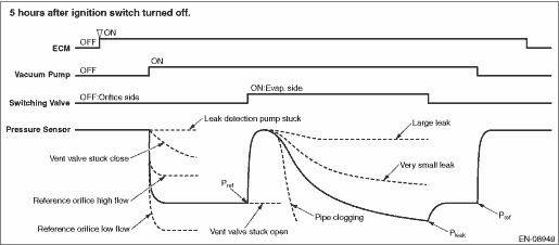
To purge the canister, after driving, perform the five hours soaking after ignition switch OFF in order to stabilize the evaporative gas status. * After 5 or 7 or 9.5 hours passed, ECM is activated by soaking timer, and the leak check is started.
Judges whether the Evaporative Leak Check Module operation is normal or not, by measuring the reference pressure status via reference orifice (0.02 inch orifice). Judge as malfunction if the reference pressure is out of specified range. Then, judge whether there is a leak or not, by comparing the pressure (leak pressure) when the reference pressure and the evaporative emission system are in negative pressure condition. Judge as system leak in the evaporative emission system if the leak pressure is higher than reference pressure. Judge as clogging of pipe if the leak pressure becomes lower than the reference pressure within the specified amount of time.
0.02 inch leak and 0.04 inch leak can be distinguished by measuring the leak pressure.
The diagnosis results are stored inside ECM until the engine is started again.
*: When the test conditions are not met in 5 hours, perform diagnosis at elapsed time of 7 hours. When the test conditions are not met in 7 hours, perform diagnosis at elapsed time of 9.5 hours.
Diagnostic item | |
Evaporative Leak Check Module system (leak check valve assembly main body) | Vacuum pump stuck Switching valve stuck to open Switching valve stuck to close Reference orifice flow large Reference orifice flow small |
Leak check | Large leak |
• 0.04 inch leak
• Fuel cap loose
• Fuel cap off
• System malfunction
Very small leak
• 0.02 inch leak
Clogging of pipe
—
OUTLINE OF DIAGNOSIS
2. COMPONENT DESCRIPTION
Evaporative Leak Check Module consists of the pressure sensor, the reference orifice (diameter of 0.02 inch), the vacuum pump which introduces the negative pressure into evaporative emission system, and the switching valve which switches the passage to introduce the negative pressure.
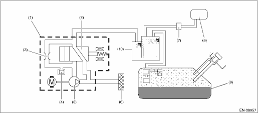
(1) | Leak check valve ASSY | (5) | Vacuum pump | (9) | Fuel tank |
(2) | Switching valve | (6) | Drain filter | (10) | Canister |
(3) | Reference orifice (0.02 inch orifice) | (7) | Purge control solenoid valve | ||
(4) | Pressure sensor | (8) | Intake manifold |
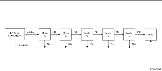
3. EXECUTION CONDITION
Secondary parameters | Execution condition |
Battery voltage | ≥ 10.9 V |
Barometric pressure | ≥ 75.1 kPa (563 mmHg, 22.2 inHg) |
Activation of soaking timer | Completed |
Intake air temperature | ≥ 4.4 °C (39.9 °F) |
Engine oil temperature | ≥ 4.4 °C (39.9 °F) |
Engine coolant temperature | ≥ 4.4 °C (39.9 °F) and < 45 °C (113 °F) |
Accumulated purge amount during previous driving cycle | ≥ Value of Map 1* |
*It takes approximately 2 min at 40 MPH
Engine coolant temperature °C (°F) | 0 (32) | 30 (86) | 35 (95) | 40 (104) | 45 (113) |
Accumulated purge amount during previous driving cycle g (oz) | 128 (4.51) | 128 (4.51) | 480 (16.93) | 800 (28.22) | 1120 (39.5) |
4. GENERAL DRIVING CYCLE
Perform the diagnosis only once when 5 or 7 or 9.5 hours has passed after ignition switch is OFF. For more detail, refer to “OUTLINE OF DIAGNOSIS”. Diagnostic Procedure with Diagnostic Trouble Code (DTC) > DTC P0455 EVAP SYSTEM (CPC) LEAK DETECTED (LARGE LEAK)">
5. DIAGNOSTIC METHOD
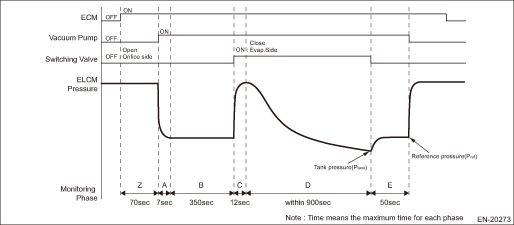
Mode | Explanation of Mode | Diagnosis Period |
A | Vacuum pump operation confirmation and characteristics stability | 7 s or less & 300 s |
B | Measurement of reference pressure for setting the target negative pressure | 40 s or less |
C | Switching valve operation confirmation | 12 s or less |
D | Clogging of pipe diagnosis and leak pressure measurement | 900 s or less |
E | Reference pressure measurement for judgment | 40 s or less |
Phase | Explanation | DTC |
Z | Measurement atmospheric pressure | — |
A | Diagnostic 1. Evaporative Leak Check Module Component Performance | P2404 |
B | Diagnostic 1. Evaporative Leak Check Module Component Performance | P2404 |
C | Diagnostic 1. Evaporative Leak Check Module Component Performance | P2404 |
D | Diagnostic 2. Pipe clogging in Evaporative Leak Check Module Measure the tank pressure (Ptank) | P1451 |
E | Diagnostic 3. Measure the referense for judgment (Pref) Detect 0.020 inch leak or 0.040 inch leak malfunctions. Diagnostic 1. Evaporative Leak Check Module Component Performance | P0455 P0456 P2404 |
Mode A (Vacuum pump operation confirmation and characteristics stability)
Purpose: Detect the vacuum pump operation trouble.
Judge as NG when the following conditions are established.
Judge as OK if the following conditions are not established, and warm up for five minutes to stabilize the vacuum pump characteristics.
Malfunction Criteria | Threshold Value | DTC |
Pressure sensor output value | > −0.2 kPa (−1.68 mmHg, −0.1 inHg) | P2404 |
Mode B (Measurement of reference pressure for setting the target negative pressure)
Judgment 1
Purpose: Judge the reference pressure stability.
Judge as NG when the following conditions are established.
Judgment 2
Purpose: Judge whether the reference pressure is within the normal range, and detect the vacuum pump and orifice malfunctions.
Judge as NG when the following conditions are established.
Malfunction Criteria | Threshold Value | DTC |
Judgment 1 | ||
|Pressure sensor maximum output value − Pressure sensor minimum output value| | > 314 Pa (2.355 mmHg, 0.1 inHg) | P2404 |
or | ||
Judgment 2 | ||
Reference pressure for setting the target negative pressure | < Value of Map 2 or > Value of Map 3 | P2404 |
Barometric pressure kPa (mmHg, inHg) | 70 (525, 20.7) | 80 (600, 23.6) | 90 (675, 26.6) | 100 (750, 29.5) |
Reference pressure for setting the target negative pressure kPa (mmHg, inHg) | −4 (−29.79, −1.2) | −4.1 (−30.593, −1.2) | −4.2 (−31.395, −1.2) | −4.3 (−32.19, −1.3) |
Barometric pressure kPa (mmHg, inHg) | 70 (525, 20.7) | 80 (600, 23.6) | 90 (675, 26.6) | 100 (750, 29.5) |
Reference pressure for setting the target negative pressure kPa (mmHg, inHg) | −0.9 (−7.065, −0.3) | −1 (−7.86, −0.3) | −1.2 (−8.663, −0.3) | −1.3 (−9.465, −0.4) |
Mode C (Switching valve operation confirmation)
Purpose: Measure the pressure increase when switching valve is changed from open to close, and detect the stuck to open/close malfunctions of the switching valve.
Judge as NG when the following conditions are established.
Malfunction Criteria | Threshold Value | DTC |
Pressure sensor output value − Reference pressure for setting the target negative pressure | < 0.2 kPa (1.68 mmHg, 0.1 inHg) | P2404 |
Mode D (Clogging of pipe diagnosis and leak pressure measurement)
(1) Clogging of pipe
Purpose: Measure the time required for the evaporative emission system to reach the target negative pressure by the vacuum pump, and detect the clogging of pipe trouble.
Judge as clogging of pipe malfunction if the evaporative emission system reaches to the target negative pressure within the specified time.
(2) Leak pressure measurement
Purpose: Measure the pressure (leak pressure) when the evaporative emission system becomes the negative pressure by the vacuum pump.
Store the pressure as a leak pressure while the following conditions are met.
Phase D
Malfunction Criteria | Threshold Value | DTC |
Time required to reach to the target negative pressure | ≤ 34000 ms | P1451 |
P0455 | ||
Leak pressure | ≥ Value of Map 6 | |
P0456 | ||
Leak pressure | > Reference pressure of 0.018 inch (Pa) | |
and | ||
< Value of Map 6 |
Reference pressure kPa (mmHg, inHg) | −4856 (−36429, −1434) | −4000 (−30007, −1181) | −2750 (−20630, −812) | −1500 (−11252, −443) | −824 (−6181, −243) |
Threshold Value kPa (mmHg, inHg) | −1785 (−13390, −527) | −1463 (−10975, −432) | −991 (−7434, −292) | −520 (−3901, −153) | −265 (−1988, −78) |
Formula for threshold value = Reference pressure ? 0.377 − 0.341
Time needed for diagnosis: 24 min
Mode E (Measurement of reference pressure for judgment)
Judgment 1
Purpose: Judge the reference pressure stability.
Judge as NG when the following conditions are established.
Judgment 2
Purpose: Judge whether the reference pressure is within the normal range, and detect the vacuum pump and orifice malfunctions. Judge the vacuum pump performance stability.
Judge as NG when the following conditions are established.
Judgment 3
Purpose: Judge the presence of evaporative emission system leak.
Judge as NG when the following conditions are established.
Malfunction Criteria | Threshold Value | DTC |
Judgment 1 | ||
|Pressure sensor maximum output value − Pressure sensor minimum output value| | > 314 Pa (2.355 mmHg, 0.1 inHg) | P2404 |
or | ||
Judgment 2 | ||
Reference pressure for judgment | < Value of Map 7 or > Value of Map 8 | P2404 |
or | ||
Judgment 3 | ||
|Reference pressure for setting the target negative pressure − Reference pressure for judgment| | > 0.9 kPa (7.058 mmHg, 0.3 inHg) | P2404 |
Reference pressure kPa (mmHg, inHg) | 70 (525, 20.7) | 80 (600, 23.6) | 90 (675, 26.6) | 100 (750, 29.5) |
Threshold Value kPa (mmHg, inHg) | −4.5 (−34.02, −1.3) | −4.6 (−34.815, −1.4) | −4.7 (−35.618, −1.4) | −4.9 (−36.42, −1.4) |
Reference pressure kPa (mmHg, inHg) | 70 (525, 20.7) | 80 (600, 23.6) | 90 (675, 26.6) | 100 (750, 29.5) |
Threshold Value kPa (mmHg, inHg) | −0.8 (−6.18, −0.2) | −0.9 (−6.983, −0.3) | −1 (−7.785, −0.3) | −1.1 (−8.58, −0.3) |
Time needed for diagnosis: 23 min
At next engine start, confirm whether the enable conditions are satisfied even though refueling has been done during soaking, and determine the malfunction.
Malfunction indicator light illumination: Illuminates when malfunction occurs in 2 continuous driving cycles.
 Dtc p0453 evap system (cpc) pressure sensor/switch circuit high
ENGINE (DIAGNOSTICS)(H4DO) > Diagnostic Procedure with Diagnostic Trouble Code (DTC)DTC P0453 EVAP SYSTEM (CPC) PRESSURE SENSOR/SWITCH CIRCUIT HIGHDTC detecting condition:Immediately at fault recog ...
 Dtc p0456 evap system (cpc) leak detected (very small leak)
ENGINE (DIAGNOSTICS)(H4DO) > Diagnostic Procedure with Diagnostic Trouble Code (DTC)DTC P0456 EVAP SYSTEM (CPC) LEAK DETECTED (VERY SMALL LEAK)NOTE:For the diagnostic procedure, refer to DTC P0455. ...
Other materials:
Note
SUNROOF/T-TOP/CONVERTIBLE TOP (SUNROOF) > Sunroof Control SystemNOTEFor operation procedures of each component of the sunroof control system, refer to the respective section.• Glass lid: Glass Lid">• Sunroof assembly: Sunroof Assembly">• Sunroof motor: Sunroof ...
Removal
CONTINUOUSLY VARIABLE TRANSMISSION(TR580) > Torque Converter AssemblyREMOVAL1. Remove the transmission assembly from the vehicle. Automatic Transmission Assembly > REMOVAL">2. Pull out the torque converter assembly horizontally.CAUTION:Do not scratch the inside of engaging parts.3. Re ...
Towing
If towing your Subaru Ascent becomes necessary, it is strongly recommended to
rely on an authorized SUBARU dealer or a professional towing service. Always follow
the correct procedures to ensure safety and prevent drivetrain damage.
WARNING
Never tow AWD versions of the Subaru Ascent with ...
