Subaru Crosstrek Service Manual: Dtc p013a o2 sensor slow response - rich to lean bank 1 sensor 2
ENGINE (DIAGNOSTICS)(H4DO) > Diagnostic Procedure with Diagnostic Trouble Code (DTC)
DTC P013A O2 SENSOR SLOW RESPONSE - RICH TO LEAN BANK 1 SENSOR 2
DTC detecting condition:
Detected when two consecutive driving cycles with fault occur.
CAUTION:
After servicing or replacing faulty parts, perform Clear Memory Mode Clear Memory Mode > OPERATION"> , and Inspection Mode Inspection Mode > PROCEDURE">.
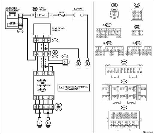
Wiring diagram:
Engine electrical system Engine Electrical System">
| STEP | CHECK | YES | NO |
1.CHECK HARNESS BETWEEN ECM AND REAR OXYGEN SENSOR CONNECTOR.
1) Turn the ignition switch to OFF.
2) Disconnect the connector from ECM.
3) Disconnect the connector from rear oxygen sensor.
4) Measure the resistance of harness between ECM connector and rear oxygen sensor connector.
Connector & terminal
(B136) No. 21 — (E25) No. 3:
Is the resistance less than 1 ??
Diagnostic Procedure with Diagnostic Trouble Code (DTC) > DTC P013A O2 SENSOR SLOW RESPONSE - RICH TO LEAN BANK 1 SENSOR 2">Go to Step 2.
Repair the harness and connector.
NOTE:
In this case, repair the following item:
• Open circuit in harness between ECM connector and rear oxygen sensor connector
• Poor contact of coupling connector
2.CHECK HARNESS BETWEEN ECM AND REAR OXYGEN SENSOR CONNECTOR.
Measure the resistance between rear oxygen sensor connector and chassis ground.
Connector & terminal
(E25) No. 3 — Chassis ground:
Is the resistance 1 M? or more?
Diagnostic Procedure with Diagnostic Trouble Code (DTC) > DTC P013A O2 SENSOR SLOW RESPONSE - RICH TO LEAN BANK 1 SENSOR 2">Go to Step 3.
Repair the short circuit to ground in harness between ECM connector and rear oxygen sensor connector.
3.CHECK REAR OXYGEN SENSOR.
Measure the resistance between rear oxygen sensor terminals.
Terminals
No. 3 — No. 4
Is the resistance less than 1 ??
Replace the rear oxygen sensor. Rear Oxygen Sensor">
Even if DTC is detected, the circuit has returned to a normal condition at this time. Reproduce the failure, and then perform the diagnosis again.
NOTE:
In this case, temporary poor contact of connector, temporary open or short circuit of harness may be the cause.
1. OUTLINE OF DIAGNOSIS
Detect the slow response of rich > lean for rear oxygen sensor output.
When the deceleration fuel cut has occurred, detect the trouble by calculating the time when the rear oxygen sensor output passes through the predetermined range of voltages.
Judge as NG when the response time is larger than the threshold value.
2. COMPONENT DESCRIPTION
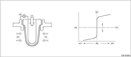
(A) | Electromotive force | (B) | Air fuel ratio | (C) | Lean |
(D) | Rich | (E) | Theoretical air fuel ratio | (F) | Comparative voltage |
(1) | Atmosphere | (2) | Exhaust gas | (3) | Electromotive force |
3. EXECUTION CONDITION
Secondary parameters | Execution condition |
Battery voltage | ≥ 10.9 V |
Current calculation time of the rear oxygen sensor heater after starting | ≥ 180000 ms |
Rear oxygen sensor voltage when fuel cut starts | ≥ 0.55 V |
Elapsed time after fuel cut | ≥ 5000 ms |
Rear oxygen sensor estimated element temperature when fuel cut starts | ≥ 500 °C (932 °F) |
4. GENERAL DRIVING CYCLE
Perform diagnosis once during deceleration fuel cut from a constant and high speed driving, when rear oxygen sensor is warmed up sufficiently.
5. DIAGNOSTIC METHOD
Detect the trouble by calculating the response time of the rear oxygen sensor during fuel cut.
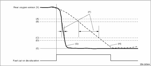
(A) | 0.55 V | (B) | 0.50 V | (C) | 0.20 V |
(D) | 0.15 V | (E) | 0 V | (F) | Diagnostic parameter |
(G) | Normal | (H) | Malfunction |
Judge as NG when the following conditions are established.
Malfunction Criteria | Threshold Value |
Time needed for rear oxygen sensor voltage to change from 0.5 V to 0.2 V | > 491 ms |
Time needed for diagnosis: Less than 1 second
Malfunction indicator light illumination: Illuminates when malfunction occurs in 2 continuous driving cycles.
 Dtc p0138 o2 sensor circuit high voltage bank 1 sensor 2
ENGINE (DIAGNOSTICS)(H4DO) > Diagnostic Procedure with Diagnostic Trouble Code (DTC)DTC P0138 O2 SENSOR CIRCUIT HIGH VOLTAGE BANK 1 SENSOR 2DTC detecting condition:Detected when two consecutive dri ...
 Dtc p013b o2 sensor slow response - lean to rich bank 1 sensor 2
ENGINE (DIAGNOSTICS)(H4DO) > Diagnostic Procedure with Diagnostic Trouble Code (DTC)DTC P013B O2 SENSOR SLOW RESPONSE - LEAN TO RICH BANK 1 SENSOR 2NOTE:For the diagnostic procedure, refer to DTC P ...
Other materials:
Inspection
FUEL INJECTION (FUEL SYSTEMS)(H4DO) > Electronic Throttle Control RelayINSPECTION1. Check that the electronic throttle control relay has no deformation, cracks or other damages.2. Measure the resistance between electronic throttle control relay terminals.Terminal No.Standard1 and 21 M? or more3 a ...
Dtc b28ac stereo camera asic
EyeSight (DIAGNOSTICS) > Diagnostic Procedure with Diagnostic Trouble Code (DTC)DTC B28AC STEREO CAMERA ASICDetected when communication error occurs due to malfunction of ASIC.DTC DETECTING CONDITION:Communication error occurs due to malfunction of ASIC.TROUBLE SYMPTOM:All functions of EyeSight s ...
Clear memory mode Operation
HVAC SYSTEM (AUTO A/C) (DIAGNOSTICS) > Clear Memory ModeOPERATION1. On «Start» display, select «Diagnosis».2. On «Vehicle selection» display, input the target vehicle information and select «Confirmed».3. On «Main Menu» display, select «Each System».4. On «Select System» display, se ...
