Subaru Crosstrek Service Manual: Dtc p0117 engine coolant temperature sensor 1 circuit low
ENGINE (DIAGNOSTICS)(H4DO) > Diagnostic Procedure with Diagnostic Trouble Code (DTC)
DTC P0117 ENGINE COOLANT TEMPERATURE SENSOR 1 CIRCUIT LOW
DTC detecting condition:
Immediately at fault recognition
Trouble symptom:
• Hard to start
• Improper idling
• Poor driving performance
CAUTION:
After servicing or replacing faulty parts, perform Clear Memory Mode Clear Memory Mode > OPERATION"> , and Inspection Mode Inspection Mode > PROCEDURE">.
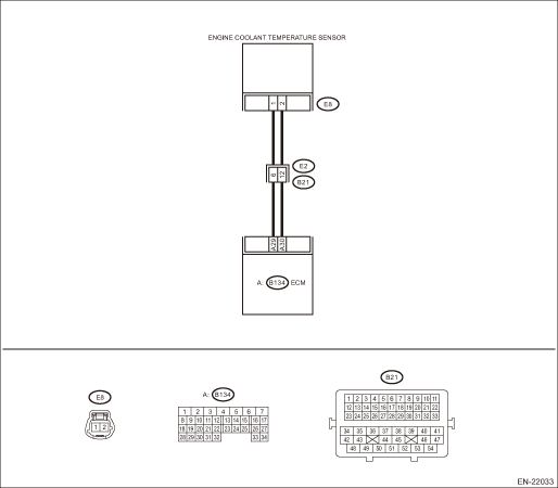
Wiring diagram:
Engine electrical system Engine Electrical System">
| STEP | CHECK | YES | NO |
1.CHECK CURRENT DATA.
1) Start the engine.
2) Read the value of «Coolant Temp.» using the Subaru Select Monitor or a general scan tool.
NOTE:
• Subaru Select Monitor
For detailed operation procedures, refer to “Current Data Display For Engine”. Subaru Select Monitor">
• General scan tool
For detailed operation procedures, refer to the general scan tool operation manual.
Is the value of «Coolant Temp.» 120°C (248°F) or more?
Diagnostic Procedure with Diagnostic Trouble Code (DTC) > DTC P0117 ENGINE COOLANT TEMPERATURE SENSOR 1 CIRCUIT LOW">Go to Step 2.
Even if DTC is detected, the circuit has returned to a normal condition at this time. Reproduce the failure, and then perform the diagnosis again.
NOTE:
In this case, temporary poor contact of connector, temporary open or short circuit of harness may be the cause.
2.CHECK HARNESS BETWEEN ECM AND ENGINE COOLANT TEMPERATURE SENSOR CONNECTOR.
1) Turn the ignition switch to OFF.
2) Disconnect the connector from ECM.
3) Disconnect the connectors from the engine coolant temperature sensor.
4) Measure the resistance between ECM connector and chassis ground.
Connector & terminal
(B134) No. 30 — Chassis ground:
Is the resistance 1 M? or more?
Replace the engine coolant temperature sensor. Engine Coolant Temperature Sensor">
Repair the short circuit to ground in harness between ECM connector and engine coolant temperature sensor connector.
1. OUTLINE OF DIAGNOSIS
Detect the open or short circuit of the engine coolant temperature sensor.
Judge as NG if out of specification.
2. COMPONENT DESCRIPTION
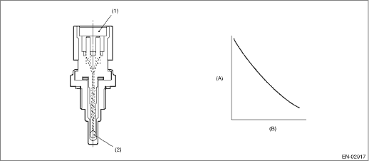
(A) | Resistance value (k?) | (B) | Temperature °C (°F) | ||
(1) | Connector | (2) | Thermistor element |
3. EXECUTION CONDITION
Secondary Parameters | Execution condition |
None |
4. GENERAL DRIVING CYCLE
Always perform the diagnosis continuously.
5. DIAGNOSTIC METHOD
If the duration of time while the following conditions are met is longer than the time indicated, judge as NG.
Malfunction Criteria | Threshold Value |
Output voltage | < 0.349 V |
Time Needed for Diagnosis: 500 ms
Malfunction Indicator Light Illumination: Illuminates as soon as a malfunction occurs.
 Dtc p0116 engine coolant temperature sensor 1 circuit range/performance
ENGINE (DIAGNOSTICS)(H4DO) > Diagnostic Procedure with Diagnostic Trouble Code (DTC)DTC P0116 ENGINE COOLANT TEMPERATURE SENSOR 1 CIRCUIT RANGE/PERFORMANCEDTC DETECTING CONDITION:Detected when two ...
 Dtc p0118 engine coolant temperature sensor 1 circuit high
ENGINE (DIAGNOSTICS)(H4DO) > Diagnostic Procedure with Diagnostic Trouble Code (DTC)DTC P0118 ENGINE COOLANT TEMPERATURE SENSOR 1 CIRCUIT HIGHDTC detecting condition:Immediately at fault recognitio ...
Other materials:
Installation
MECHANICAL(H4DO) > Cam CarrierINSTALLATION1. CAM CARRIER RH1. Insert the steel rods into ST, and set the engine so that the camshaft RH is facing up.CAUTION:• If the engine is standing on one side without inserting the steel rod into ST, engine may lose balance and fall down. Be sure to ins ...
Daytime running light system
WARNING
The brightness of the illumination of
the high beam headlights is reduced
by the daytime running light system.
The light switch must always be
turned to the " " position when it
is dark outside.
The high beam headlights will automatically
illuminate at reduced brightness
when the ...
Diagnostic procedure with phenomenon
HVAC SYSTEM (AUTO A/C) (DIAGNOSTICS) > Diagnostics with PhenomenonDIAGNOSTIC PROCEDURE WITH PHENOMENON1. NOTHING IS DISPLAYED ON THE SCREEN. NO ILLUMINATION APPEARS ON THE INDICATORTrouble symptom:• When the AUTO button is pressed with IGN ON, nothing is displayed on the screen or indicator ...
