Subaru Crosstrek Service Manual: Dtc c1531 bls off stuck
VEHICLE DYNAMICS CONTROL (VDC) (DIAGNOSTICS) > Diagnostic Procedure with Diagnostic Trouble Code (DTC)
DTC C1531 BLS OFF STUCK
DTC detecting condition:
Defective stop light switch
Trouble symptom:
• ABS does not operate.
• VDC does not operate.
• Hill start assist does not operate.
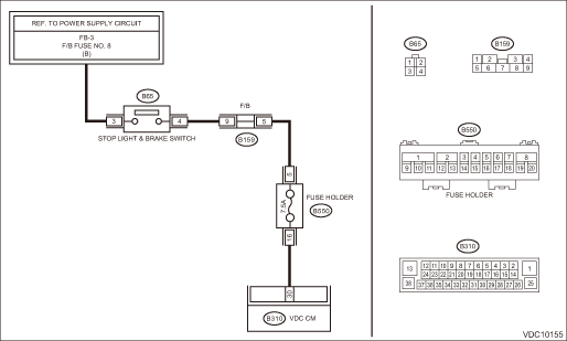
WIRING DIAGRAM:
Vehicle dynamics control system Vehicle Dynamics Control System > WIRING DIAGRAM">
| STEP | CHECK | YES | NO |
1.CHECK STOP LIGHT SWITCH.
Check the stop light switch. Stop Light Switch > INSTALLATION">
Is the check result OK?
Diagnostic Procedure with Diagnostic Trouble Code (DTC) > DTC C1531 BLS OFF STUCK">Go to Step 2.
Adjust the installation position of the stop light switch. Stop Light Switch > INSTALLATION">
2.CHECK STOP LIGHT SWITCH.
1) Turn the ignition switch to OFF.
2) Disconnect the stop light switch connector.
3) Measure the resistance of stop light switch terminals.
Terminals
No. 3 — No. 4:
Is the resistance 1 ? or less when the switch is ON (when pedal is depressed)?
Diagnostic Procedure with Diagnostic Trouble Code (DTC) > DTC C1531 BLS OFF STUCK">Go to Step 3.
Replace the stop light switch. Stop Light Switch">
3.CHECK STOP LIGHT POWER SUPPLY.
Measure the voltage between stop light switch terminal and chassis ground.
Connector & terminal
(B65) No. 3 (+) — Chassis ground (−):
Is the voltage 10 — 15 V?
Diagnostic Procedure with Diagnostic Trouble Code (DTC) > DTC C1531 BLS OFF STUCK">Go to Step 4.
Repair the stop light power supply circuit.
4.CHECK STOP LIGHT SWITCH HARNESS (CHECK FOR OPEN CIRCUIT).
1) Disconnect the connector from the VDCCM&H/U.
2) Measure the resistance between VDCCM&H/U and stop light switch.
Connector & terminal
(B65) No. 4 — (B310) No. 30:
Is the resistance less than 1 ??
Diagnostic Procedure with Diagnostic Trouble Code (DTC) > DTC C1531 BLS OFF STUCK">Go to Step 5.
Repair the stop light switch circuit.
5.CHECK POOR CONTACT OF CONNECTORS.
Is there poor contact of connector between stop light switch and VDCCM&H/U?
Repair the connector.
Diagnostic Procedure with Diagnostic Trouble Code (DTC) > DTC C1531 BLS OFF STUCK">Go to Step 6.
6.CHECK VDCCM&H/U.
1) Connect all connectors.
2) Perform the Clear Memory Mode. Clear Memory Mode">
3) Perform the Inspection Mode. Inspection Mode">
4) Read the DTC. Read Diagnostic Trouble Code (DTC)">
Is the same DTC displayed?
Replace the VDCCM only. VDC Control Module and Hydraulic Control Unit (VDCCM&H/U) > REPLACEMENT">
Diagnostic Procedure with Diagnostic Trouble Code (DTC) > DTC C1531 BLS OFF STUCK">Go to Step 7.
7.CHECK DETECTION OF OTHER DTCS FOR VDC.
Read Diagnostic Trouble Code (DTC)">
Is any other DTC displayed?
Perform the diagnosis according to DTC. List of Diagnostic Trouble Code (DTC)">
Currently, it is normal. There may have been a temporary poor contact in the harness and connector or a temporary noise interference.
 Dtc c1431 at
VEHICLE DYNAMICS CONTROL (VDC) (DIAGNOSTICS) > Diagnostic Procedure with Diagnostic Trouble Code (DTC)DTC C1431 ATDTC detecting condition:Defective TCMTrouble symptom:• ABS does not operate.& ...
 Dtc c1532 bls on stuck
VEHICLE DYNAMICS CONTROL (VDC) (DIAGNOSTICS) > Diagnostic Procedure with Diagnostic Trouble Code (DTC)DTC C1532 BLS ON STUCKDTC detecting condition:Defective stop light switchTrouble symptom:• ...
Other materials:
General diagnostic table Inspection
PARKING BRAKE > General Diagnostic TableINSPECTIONSymptomsPossible causeCorrective actionBrake draggingLever assembly - hand brake is maladjusted.Adjust.Parking brake cable does not move.Repair or replace.Parking brake shoe clearance is maladjusted.Adjust.Spring - shoe return is faulty.Replace.No ...
Control screen and panel
Control screen (main screen and station screen)
Select to display the audio source
selection screen.
Select to open the station list. Refer to
"Using aha application"
Select to fast forward the current content
item by 30 seconds.
Select to display the contents list of the
selec ...
Dtc p0023 "b" camshaft position actuator control circuit/open bank 2
ENGINE (DIAGNOSTICS)(H4DO) > Diagnostic Procedure with Diagnostic Trouble Code (DTC)DTC P0023 "B" CAMSHAFT POSITION ACTUATOR CONTROL CIRCUIT/OPEN BANK 2DTC detecting condition:Immediately at fault recognitionTrouble symptom:Improper idlingCAUTION:After servicing or replacing faulty part ...
