Subaru Crosstrek Service Manual: Dtc c0027 rear left abs sensor circuit open or short
VEHICLE DYNAMICS CONTROL (VDC) (DIAGNOSTICS) > Diagnostic Procedure with Diagnostic Trouble Code (DTC)
DTC C0027 REAR LEFT ABS SENSOR CIRCUIT OPEN OR SHORT
DTC detecting condition:
• Defective ABS wheel speed sensor (broken wire, input voltage too high)
• Defective harness connector
Trouble symptom:
• ABS does not operate.
• VDC does not operate.
• EyeSight does not operate.
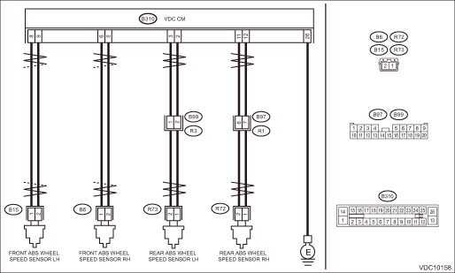
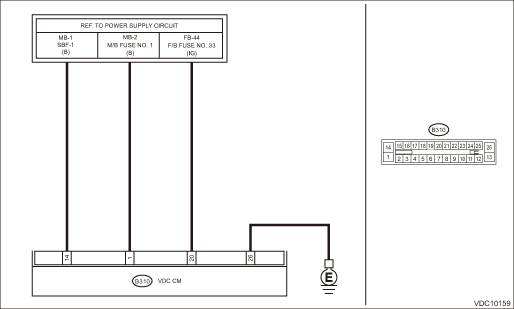
Wiring diagram:
Vehicle dynamics control system Vehicle Dynamics Control System > WIRING DIAGRAM">
| STEP | CHECK | YES | NO |
1.CHECK POOR CONTACT OF CONNECTOR.
Check if there is poor contact between VDCCM&H/U and ABS wheel speed sensor.
Is there poor contact?
Repair the connector.
Diagnostic Procedure with Diagnostic Trouble Code (DTC) > DTC C0027 REAR LEFT ABS SENSOR CIRCUIT OPEN OR SHORT">Go to Step 2.
2.CHECK HARNESS CONNECTOR BETWEEN VDCCM&H/U AND ABS WHEEL SPEED SENSOR (CHECK FOR OPEN CIRCUIT).
1) Turn the ignition switch to OFF.
2) Disconnect the connector (B310) from the VDCCM&H/U.
3) Disconnect the connector from ABS wheel speed sensor.
4) Measure the resistance between VDCCM&H/U connector and ABS wheel speed sensor connector.
Connector & terminal
DTC C0021
(B310) No. 6 — (B6) No. 1:
(B310) No. 5 — (B6) No. 2:
DTC C0023
(B310) No. 8 — (B15) No. 1:
(B310) No. 9 — (B15) No. 2:
DTC C0025
(B310) No. 12 — (R72) No. 1:
(B310) No. 11 — (R72) No. 2:
DTC C0027
(B310) No. 2 — (R73) No. 1:
(B310) No. 3 — (R73) No. 2:
Is the resistance less than 1 ??
Diagnostic Procedure with Diagnostic Trouble Code (DTC) > DTC C0027 REAR LEFT ABS SENSOR CIRCUIT OPEN OR SHORT">Go to Step 3.
Repair the harness connector between VDCCM&H/U and ABS wheel speed sensor.
3.CHECK GROUND SHORT OF HARNESS.
Measure the resistance between VDCCM&H/U connector and chassis ground.
Connector & terminal
DTC C0021
(B310) No. 6 — Chassis ground:
DTC C0023
(B310) No. 8 — Chassis ground:
DTC C0025
(B310) No. 12 — Chassis ground:
DTC C0027
(B310) No. 2 — Chassis ground:
Is the resistance 1 M? or more?
Diagnostic Procedure with Diagnostic Trouble Code (DTC) > DTC C0027 REAR LEFT ABS SENSOR CIRCUIT OPEN OR SHORT">Go to Step 4.
Repair the harness connector between VDCCM&H/U and ABS wheel speed sensor.
4.CHECK ABS WHEEL SPEED SENSOR POWER SUPPLY CIRCUIT.
1) Connect the VDCCM&H/U connector.
2) Turn the ignition switch to ON.
3) Measure the voltage between ABS wheel speed sensor connector and chassis ground.
Connector & terminal
DTC C0021
(B6) No. 2 (+) — Chassis ground (−):
DTC C0023
(B15) No. 2 (+) — Chassis ground (−):
DTC C0025
(R72) No. 2 (+) — Chassis ground (−):
DTC C0027
(R73) No. 2 (+) — Chassis ground (−):
Is the voltage 5 — 16 V?
Diagnostic Procedure with Diagnostic Trouble Code (DTC) > DTC C0027 REAR LEFT ABS SENSOR CIRCUIT OPEN OR SHORT">Go to Step 6.
Diagnostic Procedure with Diagnostic Trouble Code (DTC) > DTC C0027 REAR LEFT ABS SENSOR CIRCUIT OPEN OR SHORT">Go to Step 5.
5.CHECK VDCCM&H/U POWER SUPPLY CIRCUIT.
1) Turn the ignition switch to OFF.
2) Disconnect the VDCCM&H/U connector.
3) Turn the ignition switch to ON.
4) Measure the voltage between VDCCM&H/U connector terminals.
Connector & terminal
(B310) No. 1 (+) — (B310) No. 26 (−):
(B310) No. 14 (+) — (B310) No. 26 (−):
(B310) No. 20 (+) — (B310) No. 26 (−):
Is the voltage 10 — 15 V?
Diagnostic Procedure with Diagnostic Trouble Code (DTC) > DTC C0027 REAR LEFT ABS SENSOR CIRCUIT OPEN OR SHORT">Go to Step 6.
Check the generator, battery and VDCCM&H/U power supply circuit.
6.CHECK ABS WHEEL SPEED SENSOR SIGNAL.
1) Prepare an oscilloscope.
2) Check the ABS wheel speed sensor. Front ABS Wheel Speed Sensor > INSPECTION"> Rear ABS Wheel Speed Sensor > INSPECTION">
Does the oscilloscope indicate the waveform pattern as shown in the figure?
Diagnostic Procedure with Diagnostic Trouble Code (DTC) > DTC C0027 REAR LEFT ABS SENSOR CIRCUIT OPEN OR SHORT">Go to Step 7.
Replace the ABS wheel speed sensor. Front ABS Wheel Speed Sensor"> Rear ABS Wheel Speed Sensor">
7.CHECK VDCCM&H/U.
1) Connect all connectors.
2) Perform the Clear Memory Mode. Clear Memory Mode">
3) Perform the Inspection Mode. Inspection Mode">
4) Read the DTC. Read Diagnostic Trouble Code (DTC)">
Is the same DTC displayed?
Replace the VDCCM&H/U. VDC Control Module and Hydraulic Control Unit (VDCCM&H/U)">
Diagnostic Procedure with Diagnostic Trouble Code (DTC) > DTC C0027 REAR LEFT ABS SENSOR CIRCUIT OPEN OR SHORT">Go to Step 8.
8.CHECK DETECTION OF OTHER DTCS FOR VDC.
Read Diagnostic Trouble Code (DTC)">
Is any other DTC displayed?
Perform the diagnosis according to DTC. List of Diagnostic Trouble Code (DTC)">
Currently, it is normal. There may have been a temporary poor contact in the harness and connector or a temporary noise interference.
 Dtc c0026 rear right abs sensor signal
VEHICLE DYNAMICS CONTROL (VDC) (DIAGNOSTICS) > Diagnostic Procedure with Diagnostic Trouble Code (DTC)DTC C0026 REAR RIGHT ABS SENSOR SIGNALNOTE:For the diagnostic procedure, refer to “DTC C0 ...
 Dtc c0028 rear left abs sensor signal
VEHICLE DYNAMICS CONTROL (VDC) (DIAGNOSTICS) > Diagnostic Procedure with Diagnostic Trouble Code (DTC)DTC C0028 REAR LEFT ABS SENSOR SIGNALDTC DETECTING CONDITION:• Defective ABS wheel speed ...
Other materials:
Removal
EMISSION CONTROL (AUX. EMISSION CONTROL DEVICES)(H4DO) > EGR CoolerREMOVAL1. Disconnect the ground cable from battery.2. Drain engine coolant. Engine Coolant > REPLACEMENT">3. Remove the center exhaust pipe. Center Exhaust Pipe > REMOVAL">4. Lower the vehicle.5. Remove the ...
Precautions against vehicle modification
Always consult your SUBARU dealer if
you want to install any accessory parts to
your vehicle.
CAUTION
Do not perform any of the following
modifications. Such modifications
can interfere with proper operation
of the seatbelt pretensioners.
Attachment of any equipment
(bush bar, winches, ...
Manual rear gate
The Subaru Ascent manual rear gate can be locked and unlocked using multiple
integrated systems, providing flexibility and convenience for different situations.
Power door locking switch: Refer to "Locking and unlocking from the inside".
Keyless access with push-button start system ...
