Subaru Crosstrek Service Manual: Dtc b2a01 tel1 antenna circuit
TELEMATICS SYSTEM (DIAGNOSTICS) > Diagnostic Procedure with Diagnostic Trouble Code (DTC)
DTC B2A01 TEL1 ANTENNA CIRCUIT
Diagnosis start condition:
When ignition switch is ON.
DTC detecting condition:
Any of the followings continues for 5 seconds or more.
• TEL1 impedance is more than 1 M?. (Detached antenna, etc.)
• TEL1 impedance is less than 1 k?. (Short-circuited antenna, etc.)
Trouble symptom:
• Telematics function cannot be used.
• RED LED illuminates.
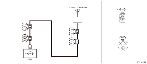
Wiring diagram:
NOTE:
For the coupling connector, refer to “WIRING SYSTEM”.
Telematics Telematics System > WIRING DIAGRAM">
CAUTION:
CommCheck is required after replacing the DCM. Telematics System > OPERATION">
| STEP | CHECK | YES | NO |
1.CHECK DTC.
Read the DTC. Diagnostic Code(s) Display">
Is DTC B2A01 displayed? (Current malfunction)
Diagnostic Procedure with Diagnostic Trouble Code (DTC) > DTC B2A01 TEL1 ANTENNA CIRCUIT">Go to Step 2.
Even if DTC is displayed, the circuit has returned to a normal condition at this time. Reproduce the failure, and then perform the diagnosis again.
In this case, temporary poor contact of connector, temporary open or short circuit of harness may be the cause.
2.CHECK HARNESS (OPEN CIRCUIT).
1) Turn the ignition switch to OFF.
2) Disconnect the antenna connector.
3) Disconnect the DCM connector.
4) Disconnect the PRG DU connector.
5) Measure the resistance between antenna connector and DCM connector.
Connector & terminal
(AN19) No. 1 — (AN24) No. 1:
Is the resistance less than 1 ??
Diagnostic Procedure with Diagnostic Trouble Code (DTC) > DTC B2A01 TEL1 ANTENNA CIRCUIT">Go to Step 3.
Repair or replace the open circuit of harness.
3.CHECK HARNESS (GROUND SHORT CIRCUIT).
Measure the resistance between DCM connector and chassis ground.
Connector & terminal
(AN19) No. 1 — Chassis ground:
Is the resistance 1 M? or more?
Diagnostic Procedure with Diagnostic Trouble Code (DTC) > DTC B2A01 TEL1 ANTENNA CIRCUIT">Go to Step 4.
Repair or replace the short circuit of the harness.
4.CHECK HARNESS (SHORT CIRCUIT TO POWER SUPPLY).
1) Turn the ignition switch to ON.
2) Measure the voltage between DCM connector and chassis ground.
Connector & terminal
(AN19) No. 1 (+) — Chassis ground (−):
Is the voltage less than 1 V?
Diagnostic Procedure with Diagnostic Trouble Code (DTC) > DTC B2A01 TEL1 ANTENNA CIRCUIT">Go to Step 5.
Repair or replace the short circuit of the harness.
5.CHECK ANTENNA.
Check the telematics antenna. Antenna">
Is the telematics antenna OK?
Replace the DCM. Data Communication Module">
Replace the telematics antenna. Antenna">

 Dtc u0452 invalid data received from restraints control module
TELEMATICS SYSTEM (DIAGNOSTICS) > Diagnostic Procedure with Diagnostic Trouble Code (DTC)DTC U0452 INVALID DATA RECEIVED FROM RESTRAINTS CONTROL MODULEDetected when CAN data from airbag CM is abnor ...
Other materials:
Installation
DIFFERENTIALS > Rear Differential Front MemberINSTALLATION1. Install the rear differential front member, and temporarily attach and tighten a new self-locking nut.2. Remove the transmission jack.3. Tighten the self-locking nut.Tightening torque:T1: 50 N·m (5.1 kgf-m, 36.9 ft-lb)T2: 110 N&m ...
Corrosion protection
Your Subaru Ascent has been carefully engineered and manufactured with advanced
corrosion-resistant materials and protective coatings. These features are designed
to preserve the vehicle’s structural integrity, maintain its refined appearance,
and ensure long-term reliability even under chal ...
Dtc u0122 lost communication with vehicle dynamics control module
Blind Spot Detection/Rear Cross Traffic Alert (DIAGNOSTICS) > Diagnostic Procedure with Diagnostic Trouble Code (DTC)DTC U0122 LOST COMMUNICATION WITH VEHICLE DYNAMICS CONTROL MODULEDetected when CAN data from VDC CM does not arrive.NOTE:Perform the diagnosis for LAN system. Basic Diagnostic Pro ...
