Subaru Crosstrek Service Manual: Dtc b1908 short in front p/t lh (to +b)
AIRBAG SYSTEM (DIAGNOSTICS) > Diagnostic Chart with Trouble Code
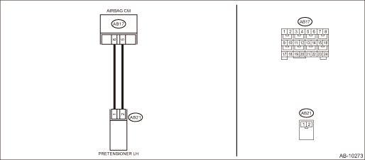
DTC B1908 SHORT IN FRONT P/T LH (TO +B)
Diagnosis start condition:
Ignition voltage is 10 V to 16 V.
DTC detecting condition:
• Seat belt pretensioner (LH) circuit is shorted to power supply.
• Pretensioner (LH) is faulty.
• Pretensioner harness (LH) is faulty.
• Airbag control module is faulty.
CAUTION:
Before performing diagnosis, refer to “CAUTION” in “General Description”. General Description > CAUTION">
Wiring diagram:
Airbag system Airbag System > WIRING DIAGRAM">
| STEP | CHECK | YES | NO |
1.CHECK POOR CONTACT OF CONNECTORS.
Check for poor contact of the connectors between the airbag control module and the seat belt pretensioner LH.
Is there poor contact?
Replace the airbag rear harness along with body harness.
Diagnostic Chart with Trouble Code > DTC B1908 SHORT IN FRONT P/T LH (TO +B)">Go to Step 2.
2.CHECK SEAT BELT PRETENSIONER.
1) Turn the ignition switch to OFF, disconnect the battery ground cable, and wait for 60 seconds or more.
2) Disconnect the connector (AB21) from seat belt pretensioner (LH).
3) Connect the connector (1N) in the test harness N to the connector (AB21).
4) Connect the airbag resistor to the connector (2N) of test harness N.
5) Connect the battery ground terminal and turn the ignition switch to ON.
Does the airbag warning light illuminate for six seconds and go off?
Replace the seat belt pretensioner (LH). Front Seat Belt">
Diagnostic Chart with Trouble Code > DTC B1908 SHORT IN FRONT P/T LH (TO +B)">Go to Step 3.
3.CHECK AIRBAG REAR HARNESS (PRETENSIONER HARNESS LH).
1) Turn the ignition switch to OFF, disconnect the battery ground cable, and wait for 60 seconds or more.
2) Disconnect the airbag resistor from the connector (2N) of test harness N.
3) Disconnect connector (AB19) from side airbag module (LH).
4) Disconnect the connector (AB31) from curtain airbag module (LH).
5) Disconnect the connectors (AB6, AB17, AB18) from airbag control module.
6) Connect the connector (1AG) in the test harness AG to the connectors (AB6, AB17, AB18).
7) Connect the battery ground terminal and turn the ignition switch to ON.
8) Measure the voltage between connector (3AG) in the test harness AG and chassis ground.
Connector & terminal
(3AG) No. 10 (+) — Chassis ground (−):
(3AG) No. 12 (+) — Chassis ground (−):
Is the voltage less than 1 V?
Diagnostic Chart with Trouble Code > DTC B1908 SHORT IN FRONT P/T LH (TO +B)">Go to Step 4.
Replace the airbag rear harness along with body harness.
4.CHECK AIRBAG CONTROL MODULE.
1) Connect all connectors.
2) Clear the memory. Clear Memory Mode">
3) Perform the Inspection Mode. Inspection Mode">
4) Read the DTC. (Current malfunction) Read Diagnostic Trouble Code (DTC)">
Is DTC B1908 displayed?
Replace the airbag control module. Airbag Control Module">
Diagnostic Chart with Trouble Code > DTC B1908 SHORT IN FRONT P/T LH (TO +B)">Go to Step 5.
5.CHECK FOR ANY OTHER DTC ON DISPLAY.
Is any other DTC displayed?
Check DTC using “List of Diagnostic Trouble Code (DTC)”. List of Diagnostic Trouble Code (DTC)">
Finish the diagnosis.
 Dtc b19f0 short in front p/t 2 rh
AIRBAG SYSTEM (DIAGNOSTICS) > Diagnostic Chart with Trouble CodeDTC B19F0 SHORT IN FRONT P/T 2 RHDiagnosis start condition:Ignition voltage is 10 V to 16 V.DTC detecting condition:• Lap seat ...
 Dtc b1905 short in front p/t lh
AIRBAG SYSTEM (DIAGNOSTICS) > Diagnostic Chart with Trouble CodeDTC B1905 SHORT IN FRONT P/T LHDiagnosis start condition:Ignition voltage is 10 V to 16 V.DTC detecting condition:• Seat belt p ...
Other materials:
Installation
AIRBAG SYSTEM > Satellite Safing SensorINSTALLATIONCAUTION:• Do not reuse the bolt and nut.Always replace with the specified new bolts and nuts.• When installing the cover - satellite safing, push the cover securely until it contacts the floor panel.• If the cover - satellite sa ...
Spark plugs
It may be difficult to replace the spark
plugs. It is recommended that you have
the spark plugs replaced by your
SUBARU dealer.
The spark plugs should be replaced
according to the maintenance schedule
in the "Warranty and Maintenance Booklet".
CAUTION
Make sure the cables are replaced in
...
Removal
LUBRICATION(H4DO) > Oil PanREMOVAL1. OIL PAN1. Disconnect the ground cable from battery. NOTE">2. Lift up the vehicle.3. Remove the under cover. Front Under Cover > REMOVAL">4. Drain the engine oil. Engine Oil > REPLACEMENT">5. Remove the front exhaust pipe. Fron ...
