Subaru Crosstrek Service Manual: Dtc b1821 open in side airbag rh
AIRBAG SYSTEM (DIAGNOSTICS) > Diagnostic Chart with Trouble Code
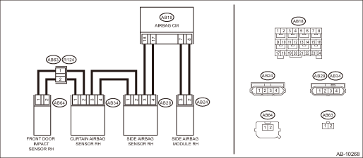
DTC B1821 OPEN IN SIDE AIRBAG RH
Diagnosis start condition:
Ignition voltage is 10 V to 16 V.
DTC detecting condition:
• Side airbag harness (RH) circuit is open.
• Side airbag module (RH) is faulty.
• Airbag control module is faulty.
CAUTION:
Before performing diagnosis, refer to “CAUTION” in “General Description”. General Description > CAUTION">
Wiring diagram:
Airbag system Airbag System > WIRING DIAGRAM">
| STEP | CHECK | YES | NO |
1.CHECK POOR CONTACT OF CONNECTORS.
Check for poor contact of the connectors between the airbag control module, side airbag module RH and the side airbag sensor RH.
Is there poor contact?
Replace the airbag rear harness along with body harness.
Diagnostic Chart with Trouble Code > DTC B1821 OPEN IN SIDE AIRBAG RH">Go to Step 2.
2.CHECK SIDE AIRBAG MODULE.
1) Turn the ignition switch to OFF, disconnect the battery ground cable, and wait for 60 seconds or more.
2) Disconnect the connector (AB24) from the side airbag module (RH), and connect the connector (1AJ) in the test harness AJ to connector (AB24).
3) Connect the airbag resistor to the test harness AJ connector (3AJ).
4) Connect the battery ground terminal and turn the ignition switch to ON.
Does the airbag warning light illuminate for 6 seconds and go off?
Replace the side airbag module (RH). Side Airbag Module > REMOVAL">
Diagnostic Chart with Trouble Code > DTC B1821 OPEN IN SIDE AIRBAG RH">Go to Step 3.
3.CHECK AIRBAG REAR HARNESS (SIDE AIRBAG MODULE HARNESS RH).
1) Turn the ignition switch to OFF, disconnect the battery ground cable, and wait for 60 seconds or more.
2) Disconnect the connector (AB26) from seat belt pretensioner (RH).
3) Disconnect the connector (AB33) from curtain airbag module (RH).
4) Disconnect the airbag resistor from test harness AJ.
5) Disconnect the connectors (AB6, AB17, AB18) from airbag control module.
6) Connect the connector (1AG) in the test harness AG to the connectors (AB6, AB17, AB18).
7) Measure the resistance between connector in the test harness AG and connector in the test harness AJ.
Connector & terminal
(5AG) No. 5 — (3AJ) No. 1:
(5AG) No. 7 — (3AJ) No. 2:
Is the resistance less than 10 ??
Diagnostic Chart with Trouble Code > DTC B1821 OPEN IN SIDE AIRBAG RH">Go to Step 4.
Replace the airbag rear harness along with body harness.
4.CHECK AIRBAG CONTROL MODULE.
1) Connect all connectors.
2) Clear the memory. Clear Memory Mode">
3) Perform the Inspection Mode. Inspection Mode">
4) Read the DTC. (Current malfunction) Read Diagnostic Trouble Code (DTC)">
Is DTC B1821 displayed?
Replace the airbag control module. Airbag Control Module">
Diagnostic Chart with Trouble Code > DTC B1821 OPEN IN SIDE AIRBAG RH">Go to Step 5.
5.CHECK FOR ANY OTHER DTC ON DISPLAY.
Is any other DTC displayed?
Check DTC using “List of Diagnostic Trouble Code (DTC)”. List of Diagnostic Trouble Code (DTC)">
Finish the diagnosis.
 Dtc b1820 short in side airbag rh
AIRBAG SYSTEM (DIAGNOSTICS) > Diagnostic Chart with Trouble CodeDTC B1820 SHORT IN SIDE AIRBAG RHDiagnosis start condition:Ignition voltage is 10 V to 16 V.DTC detecting condition:• Side airb ...
 Dtc b1822 short in side airbag rh (to ground)
AIRBAG SYSTEM (DIAGNOSTICS) > Diagnostic Chart with Trouble CodeDTC B1822 SHORT IN SIDE AIRBAG RH (TO GROUND)Diagnosis start condition:Ignition voltage is 10 V to 16 V.DTC detecting condition:&bull ...
Other materials:
Dtc b2815 power supply high voltage
EyeSight (DIAGNOSTICS) > Diagnostic Procedure with Diagnostic Trouble Code (DTC)DTC B2815 POWER SUPPLY HIGH VOLTAGEDetected when the status for the battery voltage of 16 V or more continues approximately for 5 seconds and is judged to be abnormally high voltage.Refer to DTC B2814 for DTC detectin ...
Airbag warning light remains on
AIRBAG SYSTEM (DIAGNOSTICS) > Airbag Warning Light FailureAIRBAG WARNING LIGHT REMAINS ONDetecting condition:• Airbag warning light is faulty.• Airbag control module to combination meter circuit is shorted or open.• Grounding circuit is faulty.• Airbag control module is fa ...
Radio
Usually, a problem with radio reception
does not mean there is a problem with the
radio - it is just the normal result of
conditions outside the vehicle.
For example, nearby buildings and terrain
can interfere with FM reception. Power
lines or phone wires can interfere with AM
signals. And ...
