Subaru Crosstrek Service Manual: Dtc b1801 open in driver s airbag
AIRBAG SYSTEM (DIAGNOSTICS) > Diagnostic Chart with Trouble Code
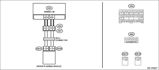
DTC B1801 OPEN IN DRIVER’S AIRBAG
Diagnosis start condition:
Ignition voltage is 10 V to 16 V.
DTC detecting condition:
• Airbag main harness circuit is open.
• Airbag module harness (driver’s side) circuit is open.
• Roll connector is open.
• Driver’s airbag module is faulty.
• Airbag control module is faulty.
CAUTION:
Before performing diagnosis, refer to “CAUTION” in “General Description”. General Description > CAUTION">
NOTE:
Prior to starting work, prepare two AIRBAG RESISTORs (98299PA040).
Wiring diagram:
Airbag system Airbag System > WIRING DIAGRAM">
| STEP | CHECK | YES | NO |
1.CHECK POOR CONTACT OF CONNECTORS.
Check for poor contact of the connectors between the airbag control module and the driver’s airbag module.
Is there poor contact?
Replace the airbag harness.
Diagnostic Chart with Trouble Code > DTC B1801 OPEN IN DRIVER’S AIRBAG">Go to Step 2.
2.CHECK DRIVER’S AIRBAG MODULE.
1) Turn the ignition switch to OFF, disconnect the battery ground cable, and wait for 60 seconds or more.
2) Remove the driver’s airbag module.
3) Connect the connector (1N) in the test harness N to the connector (AB38).
4) Connect the airbag resistor to the connector (2N) of test harness N.
5) Connect the connector (1Q) in the test harness Q to connector (AB37).
6) Connect the airbag resistor to the connector (2Q) in the test harness Q.
7) Connect the battery ground terminal and turn the ignition switch to ON.
Does the airbag warning light illuminate for six seconds and go off?
Replace the driver’s airbag module. Driver’s Airbag Module">
Diagnostic Chart with Trouble Code > DTC B1801 OPEN IN DRIVER’S AIRBAG">Go to Step 3.
3.CHECK ROLL CONNECTOR AND AIRBAG MAIN HARNESS (DRIVER’S AIRBAG HARNESS).
1) Turn the ignition switch to OFF, disconnect the battery ground cable, and wait for 60 seconds or more.
2) Remove the console front panel and disconnect the connector (AB9).
3) Disconnect the driver’s knee airbag module connector (AB66).
4) Disconnect the airbag resistor from the connector (2N) in test harness N.
5) Disconnect the airbag resistor from the connector (2Q) of test harness Q.
6) Disconnect the connectors (AB6, AB17, AB18) from airbag control module.
7) Measure the resistance between connector (2Q) terminals in test harness Q.
Connector & terminal
(2Q) No. 1 — (2Q) No. 2:
Is the resistance less than 10 ??
Diagnostic Chart with Trouble Code > DTC B1801 OPEN IN DRIVER’S AIRBAG">Go to Step 5.
Diagnostic Chart with Trouble Code > DTC B1801 OPEN IN DRIVER’S AIRBAG">Go to Step 4.
4.CHECK ROLL CONNECTOR.
1) Remove the instrument panel lower cover and column cover, and disconnect the connector (AB7) from (AB2).
2) Measure the resistance between connector (2Q) terminals in test harness Q.
Connector & terminal
(2Q) No. 1 — (2Q) No. 2:
Is the resistance less than 10 ??
Replace the airbag main harness along with body harness.
Replace the roll connector. Roll Connector">
5.CHECK AIRBAG CONTROL MODULE.
1) Connect all connectors.
2) Clear the memory. Clear Memory Mode">
3) Perform the Inspection Mode. Inspection Mode">
4) Read the DTC. (Current malfunction) Read Diagnostic Trouble Code (DTC)">
Is DTC B1801 displayed?
Replace the airbag control module. Airbag Control Module">
Diagnostic Chart with Trouble Code > DTC B1801 OPEN IN DRIVER’S AIRBAG">Go to Step 6.
6.CHECK FOR ANY OTHER DTC ON DISPLAY.
Is any other DTC displayed?
Check DTC using “List of Diagnostic Trouble Code (DTC)”. List of Diagnostic Trouble Code (DTC)">
Finish the diagnosis.
 Dtc b1800 short in driver s airbag
AIRBAG SYSTEM (DIAGNOSTICS) > Diagnostic Chart with Trouble CodeDTC B1800 SHORT IN DRIVER’S AIRBAGDiagnosis start condition:Ignition voltage is 10 V to 16 V.DTC detecting condition:• Ai ...
 Dtc b1802 short in driver s airbag (to ground)
AIRBAG SYSTEM (DIAGNOSTICS) > Diagnostic Chart with Trouble CodeDTC B1802 SHORT IN DRIVER’S AIRBAG (TO GROUND)Diagnosis start condition:Ignition voltage is 10 V to 16 V.DTC detecting conditio ...
Other materials:
Dtc b1409 scu communication
IMMOBILIZER (DIAGNOSTICS) > Diagnostic Procedure with Diagnostic Trouble Code (DTC)DTC B1409 SCU COMMUNICATIONDTC detecting condition:Communication failure between body integrated unit and security control moduleCAUTION:When the body integrated unit is replaced, registration of the immobilizer sy ...
Dtc u0416 invalid data received from vehicle dynamics control module
LAN SYSTEM (DIAGNOSTICS) > Diagnostic Procedure with Diagnostic Trouble Code (DTC)DTC U0416 INVALID DATA RECEIVED FROM VEHICLE DYNAMICS CONTROL MODULEDTC DETECTING CONDITION:Data from VDCCM is faulty.TROUBLE SYMPTOM:ABS warning light and VDC warning light illuminate.STEPCHECKYESNO1.CHECK PERFORMI ...
Ebd warning light, abs warning, vdc off indicator light, vdc warning light and vdc indicator light do not come on
VEHICLE DYNAMICS CONTROL (VDC) (DIAGNOSTICS) > Warning Light Illumination PatternEBD WARNING LIGHT, ABS WARNING, VDC OFF INDICATOR LIGHT, VDC WARNING LIGHT AND VDC INDICATOR LIGHT DO NOT COME ONDetecting condition:Defective combination meterTrouble symptom:When the ignition switch is turned to ON ...
