Subaru Crosstrek Service Manual: Assembly
MECHANICAL(H4DO) > Cam Carrier
ASSEMBLY
1. CAM CARRIER RH
1. Install the filter to the cam carrier RH.
NOTE:
Use a new filter.
Filter insert position:
Cam carrier RH end face 0+0 −0.5 mm (+0 −0.0197 in) position
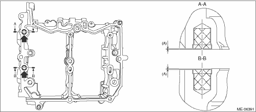
(A) | 0 — 0.5 mm (0 — 0.0197 in) |
2. Set the intake camshaft RH and the exhaust camshaft RH to the cam carrier RH.
NOTE:
Apply engine oil to the journals of cam carrier RH before setting the intake camshaft RH and exhaust camshaft RH.
3. Install the front camshaft cap RH, intake center camshaft cap RH, intake rear camshaft cap RH, exhaust center camshaft cap RH and exhaust rear camshaft cap RH.
(1) Apply liquid gasket to the mating surface of front camshaft cap RH, intake rear camshaft cap RH and exhaust rear camshaft cap RH as shown in the figure.
CAUTION:
• Do not apply liquid gasket excessively. Applying excessively may cause excess gasket to flow toward camshaft journal, resulting in engine seizure.
• Do not apply liquid gasket excessively to the intake center camshaft cap RH and exhaust center camshaft cap RH.
NOTE:
• Before applying liquid gasket, degrease the old liquid gasket seal surface of the front camshaft cap RH, intake rear camshaft cap RH, exhaust rear camshaft cap RH, and cam carrier RH.
• Install within 5 min. after applying liquid gasket.
Liquid gasket:
THREE BOND 1217G (Part No. K0877Y0100), THREE BOND 1217H or equivalent
Liquid gasket applying diameter:
Mating surfaces other than range A
2±0.5 mm (0.0787±0.0197 in)
Mating surfaces of range A
3.5±0.5 mm (0.1378±0.0197 in)
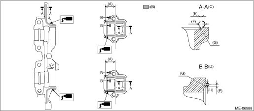
(A) | 28.5 mm (1.122 in) | (D) | Liquid gasket applying position of mating surfaces other than range A | (G) | Chamfer edge |
(B) | Range A | (E) | 1 mm (0.0394 in) or less | (H) | φ2±0.5 mm (0.0787±0.0197 in) |
(C) | Liquid gasket applying position of mating surfaces of range A | (F) | φ3.5±0.5 mm (0.1378±0.0197 in) |
(2) Apply engine oil to the journals of each camshaft cap before setting the camshaft cap.
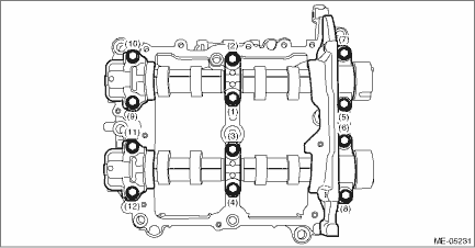
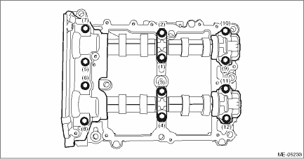
(3) Tighten the bolts which secure front camshaft cap RH, intake center camshaft cap RH, intake rear camshaft cap RH, exhaust center camshaft cap RH and exhaust rear camshaft cap RH in numerical order as shown in the figure.
Tightening torque:
18 N·m (1.8 kgf-m, 13.3 ft-lb)
2. CAM CARRIER LH
1. Install the filter to the cam carrier LH.
NOTE:
Use a new filter.
Filter insert position:
Cam carrier LH end face 0+0 −0.5 mm (+0 −0.0197 in) position
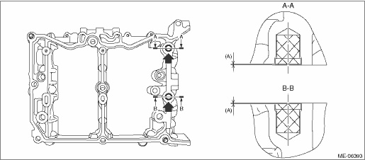
(A) | 0 — 0.5 mm (0 — 0.0197 in) |
2. Set the intake camshaft LH and the exhaust camshaft LH to the cam carrier LH.
NOTE:
Apply engine oil to the journals of cam carrier LH before setting the intake camshaft LH and exhaust camshaft LH.
3. Install the front camshaft cap LH, intake center camshaft cap LH, intake rear camshaft cap LH, exhaust center camshaft cap LH and exhaust rear camshaft cap LH.
(1) Apply liquid gasket to the mating surface of front camshaft cap LH, intake rear camshaft cap LH and exhaust rear camshaft cap LH as shown in the figure.
CAUTION:
• Do not apply liquid gasket excessively. Applying excessively may cause excess gasket to flow toward camshaft journal, resulting in engine seizure.
• Do not apply liquid gasket excessively to the intake center camshaft cap LH and exhaust center camshaft cap LH.
NOTE:
• Before applying liquid gasket, degrease the old liquid gasket seal surface of the front camshaft cap LH, intake rear camshaft cap LH, exhaust rear camshaft cap LH, and cam carrier LH.
• Install within 5 min. after applying liquid gasket.
Liquid gasket:
THREE BOND 1217G (Part No. K0877Y0100), THREE BOND 1217H or equivalent
Liquid gasket applying diameter:
Mating surfaces other than ranges A, B and C
2±0.5 mm (0.0787±0.0197 in)
Mating surfaces of ranges A and C
3.5±0.5 mm (0.1378±0.0197 in)
Mating surfaces of range B
3+0.5 −0 mm (0.1181+0.0197 −0 in)
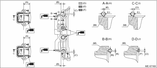
(A) | 28.5 mm (1.122 in) | (G) | Liquid gasket applying position of mating surfaces of range A | (M) | Chamfer edge |
(B) | 11.6 mm (0.4567 in) | (H) | Liquid gasket applying position of mating surfaces of range B | (N) | φ3+0.5 −0 mm (+0.0197 −0 in) |
(C) | 5.1 mm (0.2008 in) | (I) | Liquid gasket applying position of mating surfaces of range C | (O) | 1 mm (0.0394 in) or less |
(D) | Range A | (J) | Liquid gasket applying position of mating surfaces other than range A, range B and range C | (P) | φ2±0.5 mm (0.0787±0.0197 in) |
(E) | Range B | (K) | 0.5 mm (0.0197 in) | ||
(F) | Range C | (L) | φ3.5±0.5 mm (0.1378±0.0197 in) |
(2) Apply engine oil to the journals of each camshaft cap before setting the camshaft cap.
(3) Tighten the bolts which secure front camshaft cap LH, intake center camshaft cap LH, intake rear camshaft cap LH, exhaust center camshaft cap LH and exhaust rear camshaft cap LH in numerical order as shown in the figure.
Tightening torque:
18 N·m (1.8 kgf-m, 13.3 ft-lb)
 Cam carrier
...
 Removal
MECHANICAL(H4DO) > Cam CarrierREMOVAL1. CAM CARRIER RH1. Remove the engine from the vehicle. Engine Assembly > REMOVAL">2. Remove the chain cover. Chain Cover > REMOVAL">3. ...
Other materials:
Procedure
HVAC SYSTEM (HEATER, VENTILATOR AND A/C) > Compressor OilPROCEDURENOTE:Before making repairs, perform the oil return operation to return the compressor oil in circulation with the refrigerant to the compressor assembly.1. Increase the engine speed to 1,500 r/min.2. Turn the A/C switch to ON.3. Tu ...
ABS (Anti-lock Brake System)
The ABS system in the Subaru Ascent is engineered to prevent wheel lock-up during
sudden or emergency braking, especially on slippery or uneven road surfaces. By
maintaining wheel rotation, the system allows the driver to retain steering control
and directional stability, reducing the risk of ...
Caution
POWER ASSISTED SYSTEM (POWER STEERING) > General DescriptionCAUTION• Wear appropriate work clothing, including a helmet, protective goggles and protective shoes when performing any work.• Before removal, installation or disassembly, be sure to clarify the failure. Avoid unnecessary re ...
