Subaru Crosstrek Service Manual: Dtc p2122 throttle/pedal position sensor/switch "d" circuit low
ENGINE (DIAGNOSTICS)(H4DO) > Diagnostic Procedure with Diagnostic Trouble Code (DTC)
DTC P2122 THROTTLE/PEDAL POSITION SENSOR/SWITCH "D" CIRCUIT LOW
DTC detecting condition:
Immediately at fault recognition
Trouble symptom:
• Improper idling
• Poor driving performance
CAUTION:
After servicing or replacing faulty parts, perform Clear Memory Mode Clear Memory Mode > OPERATION"> , and Inspection Mode Inspection Mode > PROCEDURE">.
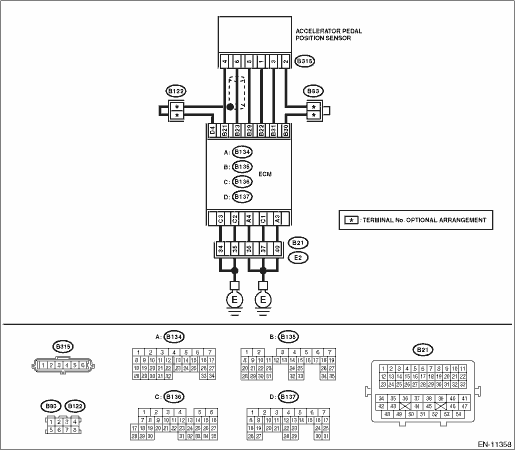
Wiring diagram:
Engine electrical system Engine Electrical System">
| STEP | CHECK | YES | NO |
1.CHECK HARNESS BETWEEN ECM AND ACCELERATOR PEDAL POSITION SENSOR CONNECTOR.
1) Turn the ignition switch to OFF.
2) Disconnect the connector from ECM.
3) Disconnect the connector from the accelerator pedal position sensor.
4) Measure the resistance between ECM connector and chassis ground.
Connector & terminal
(B135) No. 21 — Chassis ground:
(B135) No. 23 — Chassis ground:
(B135) No. 23 — (B137) No. 4:
Is the resistance 1 M? or more?
Diagnostic Procedure with Diagnostic Trouble Code (DTC) > DTC P2122 THROTTLE/PEDAL POSITION SENSOR/SWITCH "D" CIRCUIT LOW">Go to Step 2.
Repair the short circuit to ground in harness between ECM connector and accelerator pedal position sensor connector.
2.CHECK SHORT CIRCUIT INSIDE THE ECM.
1) Connect the connector to ECM.
2) Measure the resistance between accelerator pedal position sensor connector and chassis ground.
Connector & terminal
(B315) No. 6 — Chassis ground:
Is the resistance 1 M? or more?
Replace the accelerator pedal. Accelerator Pedal">
Repair the short circuit to ground in harness between ECM connector and accelerator pedal position sensor connector. Replace the ECM if defective. Engine Control Module (ECM)">
1. OUTLINE OF DIAGNOSIS
Detect the open or short circuit of accelerator pedal position sensor 1.
Judge as NG if out of specification.
2. COMPONENT DESCRIPTION
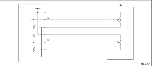
(1) | Engine control module (ECM) | (3) | Accelerator pedal position sensor 2 signal | (4) | Accelerator pedal position sensor |
(2) | Accelerator pedal position sensor 1 signal |
3. EXECUTION CONDITION
Secondary Parameters | Execution condition |
Battery voltage | ≥ 6 V |
4. GENERAL DRIVING CYCLE
Always perform the diagnosis continuously.
5. DIAGNOSTIC METHOD
If the duration of time while the following conditions are met is longer than the time indicated, judge as NG.
Malfunction Criteria | Threshold Value |
Sensor 1 input voltage | < 0.298 V |
Time Needed for Diagnosis: 100 ms
Malfunction Indicator Light Illumination: Illuminates as soon as a malfunction occurs.
 Dtc p2119 throttle actuator "a" control throttle body range/performance
ENGINE (DIAGNOSTICS)(H4DO) > Diagnostic Procedure with Diagnostic Trouble Code (DTC)DTC P2119 THROTTLE ACTUATOR "A" CONTROL THROTTLE BODY RANGE/PERFORMANCENOTE:For the diagnostic procedur ...
 Dtc p2123 throttle/pedal position sensor/switch "d" circuit high
ENGINE (DIAGNOSTICS)(H4DO) > Diagnostic Procedure with Diagnostic Trouble Code (DTC)DTC P2123 THROTTLE/PEDAL POSITION SENSOR/SWITCH "D" CIRCUIT HIGHDTC detecting condition:Immediately at ...
Other materials:
Removal
EXTERIOR/INTERIOR TRIM > Door TrimREMOVAL1. FRONT DOOR1. Disconnect the ground cable from battery. NOTE">2. Remove the trim panel - front door.(1) Attach the protective tape (a).(2) Open the cover and remove the screw.(3) Remove the clips, and remove the trim panel - front door from the ...
Dtc b1430 in-vehicle (post evaporator) temperature sensor circuit open
HVAC SYSTEM (AUTO A/C) (DIAGNOSTICS) > Diagnostic Procedure with Diagnostic Trouble Code (DTC)DTC B1430 IN-VEHICLE (POST EVAPORATOR) TEMPERATURE SENSOR CIRCUIT OPENDTC detecting condition:In-vehicle sensor circuit is open.Trouble symptom:In-vehicle air temperature is falsely recognized as 25& ...
Operation
AUTO HEADLIGHT BEAM LEVELER SYSTEM (DIAGNOSTICS) > Subaru Select MonitorOPERATION• For detailed operation procedures, refer to “Application help”.• If the auto headlight beam leveler CM can not communicate with Subaru Select Monitor, perform “COMMUNICATION FOR INITIA ...
